10.7 LED and DIP Switch for the Communication unit
10-37
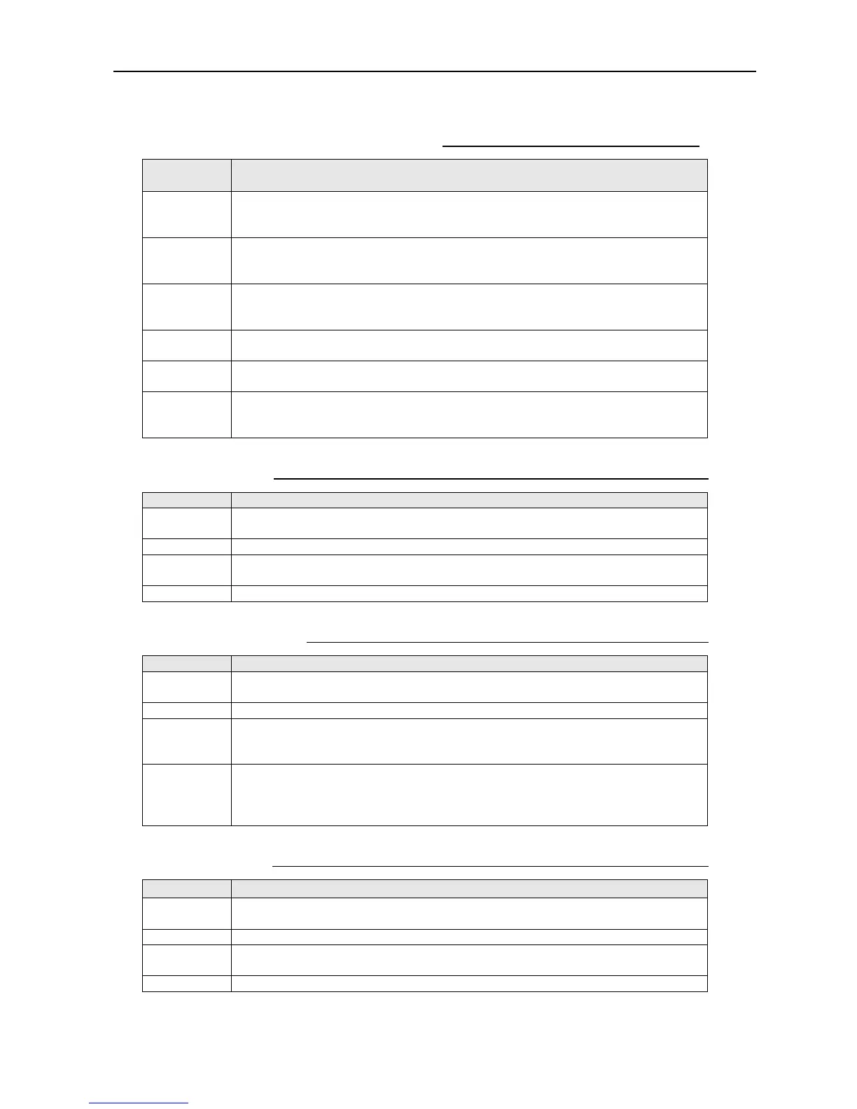
Table 10.7.3 LED for the MODEM board
LED Description
CR1
CR1(chip3216,YLW_GREEN): LED for debugging DSP1
Turned off when DSP1 is not activated yet, and blinks when it is activated (the
blinking speed varies according to the software load).
CR4
CR4(chip3216,YLW_GREEN): LED for debugging DSP2
Turned off when DSP2 is not activated yet, and blinks when it is activated (the
blinking speed varies according to the software load).
CR5
CR5(chip3216,YLW_GREEN): LED for debugging CPU
Turned off when CPU is not activated yet, and blinks when it is activated (the
blinking speed varies according to the software load).
CR6
CR6(chip3216,YLW_GREEN): LED for debugging Rx_FPGA
Turned off when Rx_FPGA is not activated yet, and blinks when it is activated.
CR8
CR8(chip3216,YLW_GREEN): LED for debugging Tx_FPGA
Turned off when FPGA is not activated yet, and blinking after activated.
CR14
CR14(chip3216,YLW_GREEN): LED for debugging DSP3
Turned off when FPGA is not activated yet, and blinks when it is activated (the
blinking speed varies according to the software load).
Table 10.7.4 MODEM board: S2 (DIP_SW for debugging Tx_FPGA)
S2 (All OFF) Function
#1
Select the signal to be output the debugging pin. Make the selection by the
combination of the 2 bits of #1 and 2.
#2 Same as above
#3
ON/OFF setting for the output to the debugging pin. When output is made:
ON, when output is not made: OFF.
#4 Not used
Table 10.7.5 MODEM board: S3 (DIP_SW for debugging CPU)
S3 (All OFF) Function
#1
Switching for DEBUGSIO. When set to ON, the COM port will be the debug
output port.
#2 Switching between WDTON/OFF. When set to ON, it will be set to WDTOFF.
#3
Switching between the real USIM/DUMMYUSIM, When set to ON, the
DUMMY USIM will be used.
Note) DUMMY USIM: SIM information is to be input via the LAN
#4
Antenna connected / disconnected mode
When set to ON, the system mode will be set to that where test is available
without connecting to the Antenna (where no searching processes, etc. are
implemented).
Table 10.7.6 MODEM board: S4 (DIP_SW for debugging Rx_FPGA)
S4 (All OFF) Function
#1
Select the signal to be output the debugging pin. Make the selection by the
combination of the 2 bits of #1 and 2.
#2 Same as above
#3
ON/OFF setting for the output to the debugging pin. When output is made:
ON, when output is not made: OFF.
#4 Not used

 Loading...