11.1 Communication unit: FB-2000
11-12
11.1.5 PANEL: 16P0227
PANEL board is connected to MODEM board.
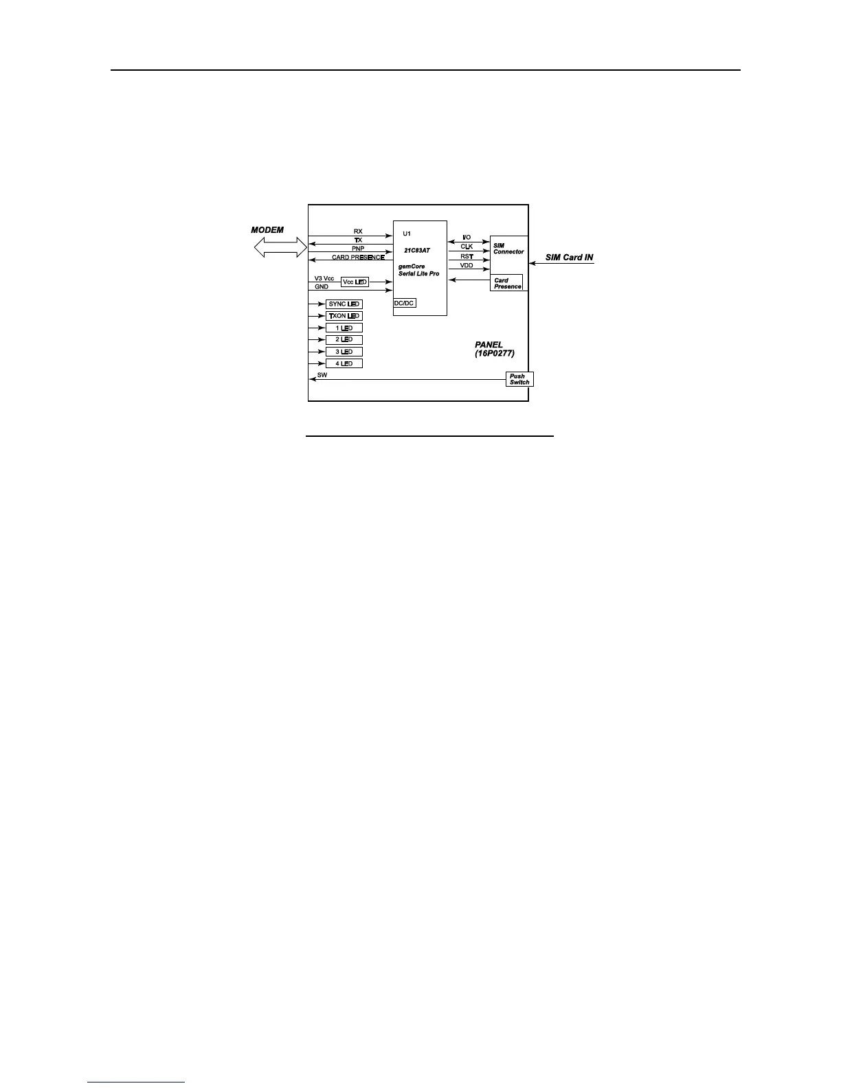
PANEL board consists of the SIM card interface and the panel LED, and the reset switch.
Fig. 11.1.9 PANEL board block diagram
1. SIM
Make sure to turn off the power before inserting / taking out the SIM card.
The SIM card and the MODEM board are communicating via the U1: SIM interface IC.
2. LED
The operations for each LED and the Reset switch are described on page 10-34.
Normally, each LED is lighted excluding TX LED.
x When READY LED is lighted, which means that the Antenna is in tracking status and
that registration for the FB network is completed, this indicates that the system is in
an available status.
x TX LED will be lighted when data is transmitted.
x The STATUS LED 1 to 4 will indicate the system abnormality identification by their
LED lighting statuses.
3. Reset SW
Turn the power on by pressing the button switch located inside the SIM cover. Make sure
to press this switch for 3 seconds or longer. Release your hand from the switch after you
have confirmed that all LEDs are blinking at high speed excluding POWER LED. Now
you have completed the initialization process.
All settings in the Communication unit are initialized, and are restored to the statues at
shipment.
 Loading...