I
-
Channel Measurements
Making Channel Measurements
5.
Press Select Test Sig if you need to change the test signal selection.
a.
Press FCC COMPOSIT to select the FCC composite test signal, or
NTC 7 CUMPOSIT to select the NTC 7 composite test signal. To assist
in test signal identification a small schematic diagram of the test signal
is displayed at the top of the screen.
b.
Press Prev menu.
6.
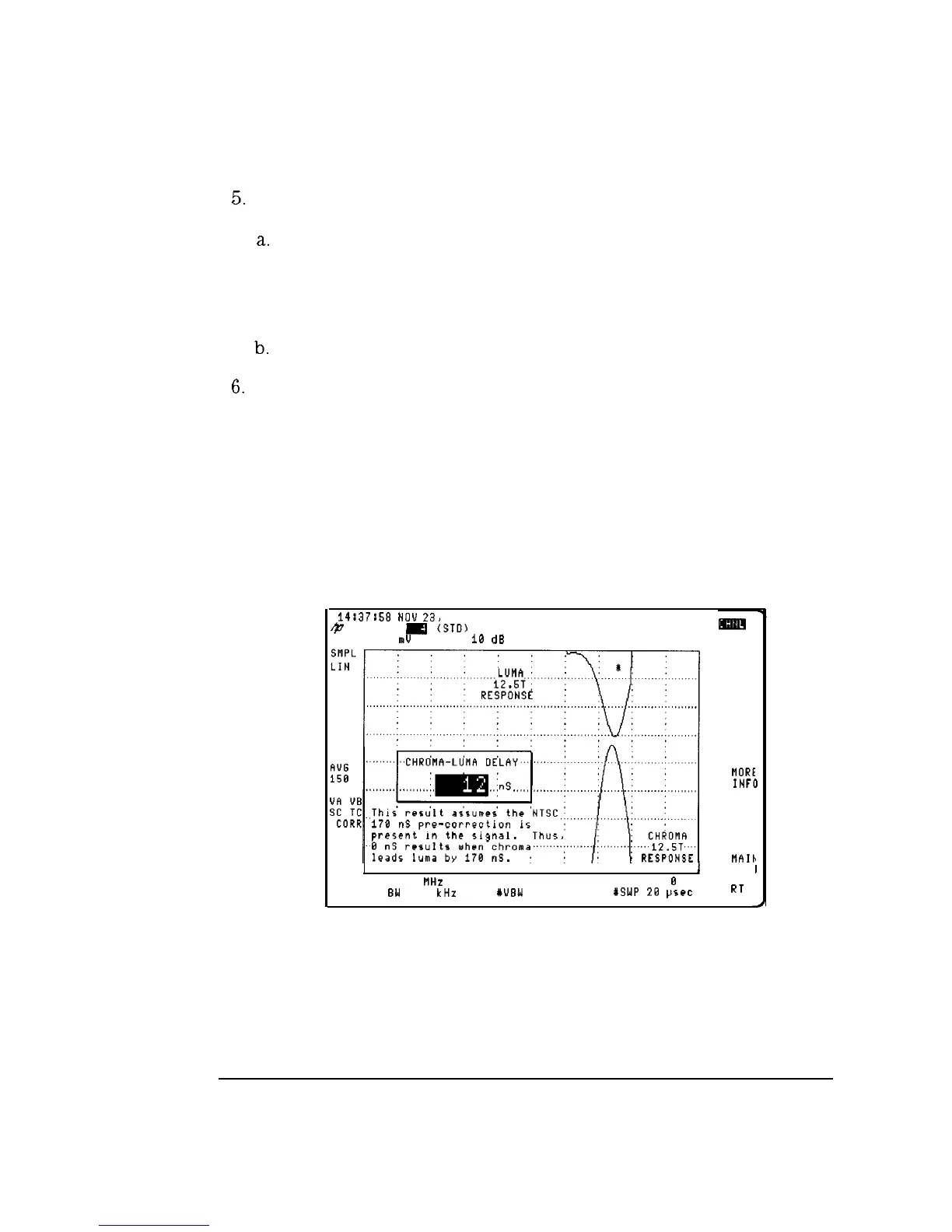
Press CONTINUE to perform the test.
The result of the measurement is displayed on the analyzer display. An
offset of 170 ns is added to the result so that it will agree with tests done
using a demodulator with 170 ns of delay. Modulators should be set
for 170 ns precorrection. FCC requires measurements relative to this
precorrection. The FCC tolerance is +/-170 ns.
7. Press MORE INFO to display chrominance to luminance response
information. See Figure 2-16
14:37:58
NOU
23,
1993
@
CHANNEL
Ic)
(3.10)
REF 6.903
m!J
AT
10
dB
I
I I
I
CENTER 78.829 MHz
SPAN
8
Hz
YRES
BW
30.3 kHz
YUBW
3 MHz
WSWP
28
psec
MORE
INF(
)
I
I
J
MAIC
MEN1
RT
Figure 2-16. Chrominance to luminance, More Information
2-24
 Loading...


