I
-
Channel Measurements
Making Channel Measurements
NOTE
The displayed video is inverted from how it would appear on a waveform analyzer (that is, sync is
displayed at the top in this test and would be displayed at the bottom with a waveform analyzer).
/’
e. Press TV TRIG ODD FLD to change to odd field or
TV TRIG EVEN FLD to change to even field.
f.
Press TV TRIG VERT INT to trigger on both fields.
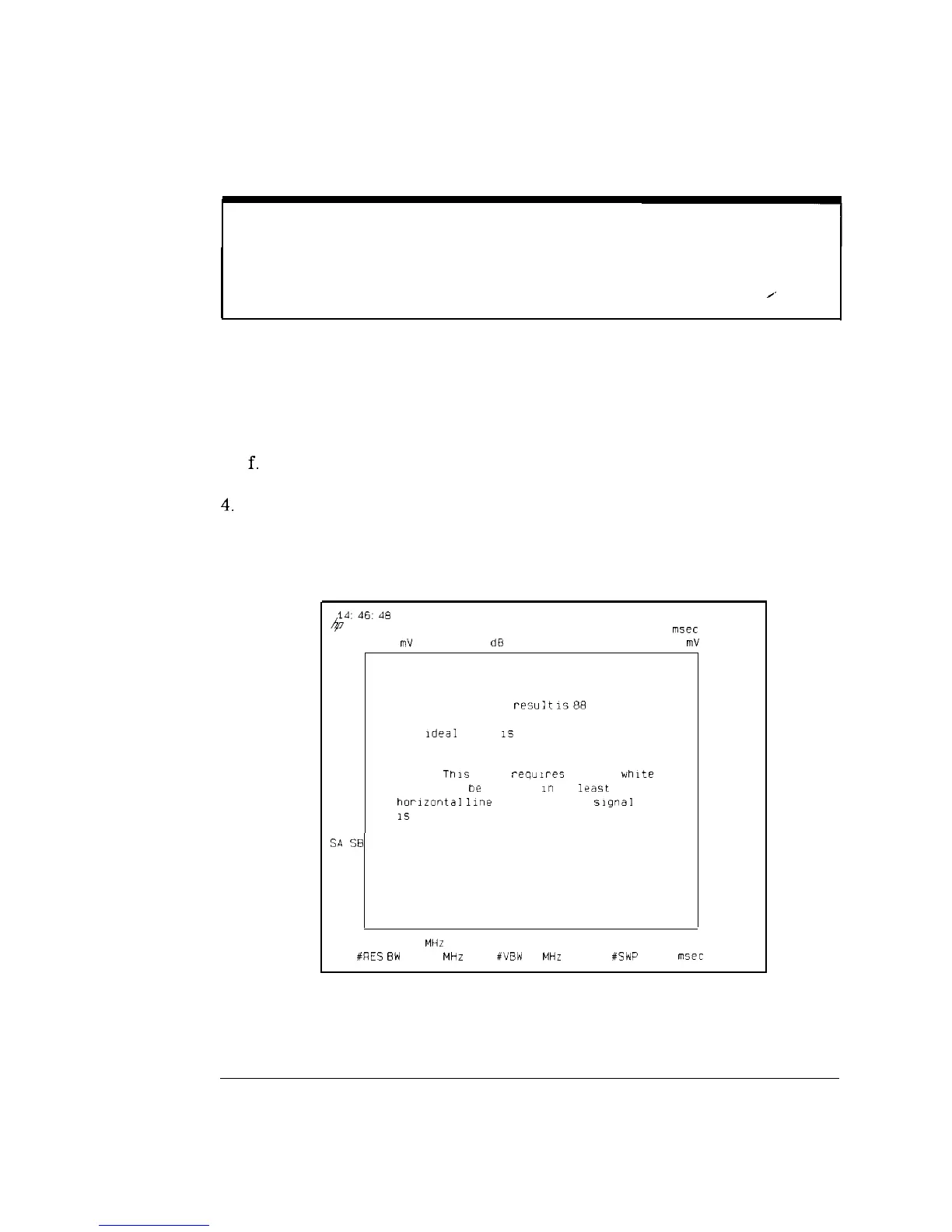
4.
Press MORE INFO to display the test results, ideal value, and other
measurement considerations. See Figure 2-22. Press RETURN when
finished.
14:46:48
NOV 23. 1993
4
MKR 7 3000
msec
REF 83.86
mV
AT 10
dE!
10.230 mV
SMPL
LIN
DEPTH OF MODULATION TEST
The current test
resu:t
1588
0%
The
Ideal
value
1s
87.5%.
NOTE'
This
test
requ,res
that a
white
reference
be
present
I"
at
least
one
horizontal
line
and that the
slgnal
IS
not scrambled.
SA
SE
SC FC
CORR
0
RETURN
CENTER 67 275 MHz
SPAN 0
HZ
#RES
BW
1.0 MHz
#VBW
1
MHz #SWP 20.0
lll5ec
Figure 2-22. Depth of Video Modulation, More Information
2-34
 Loading...


