be found on both the GUI and also in each input fast strip. This section is optional and
assigned on a channel-by-channel basis.
4
1
5
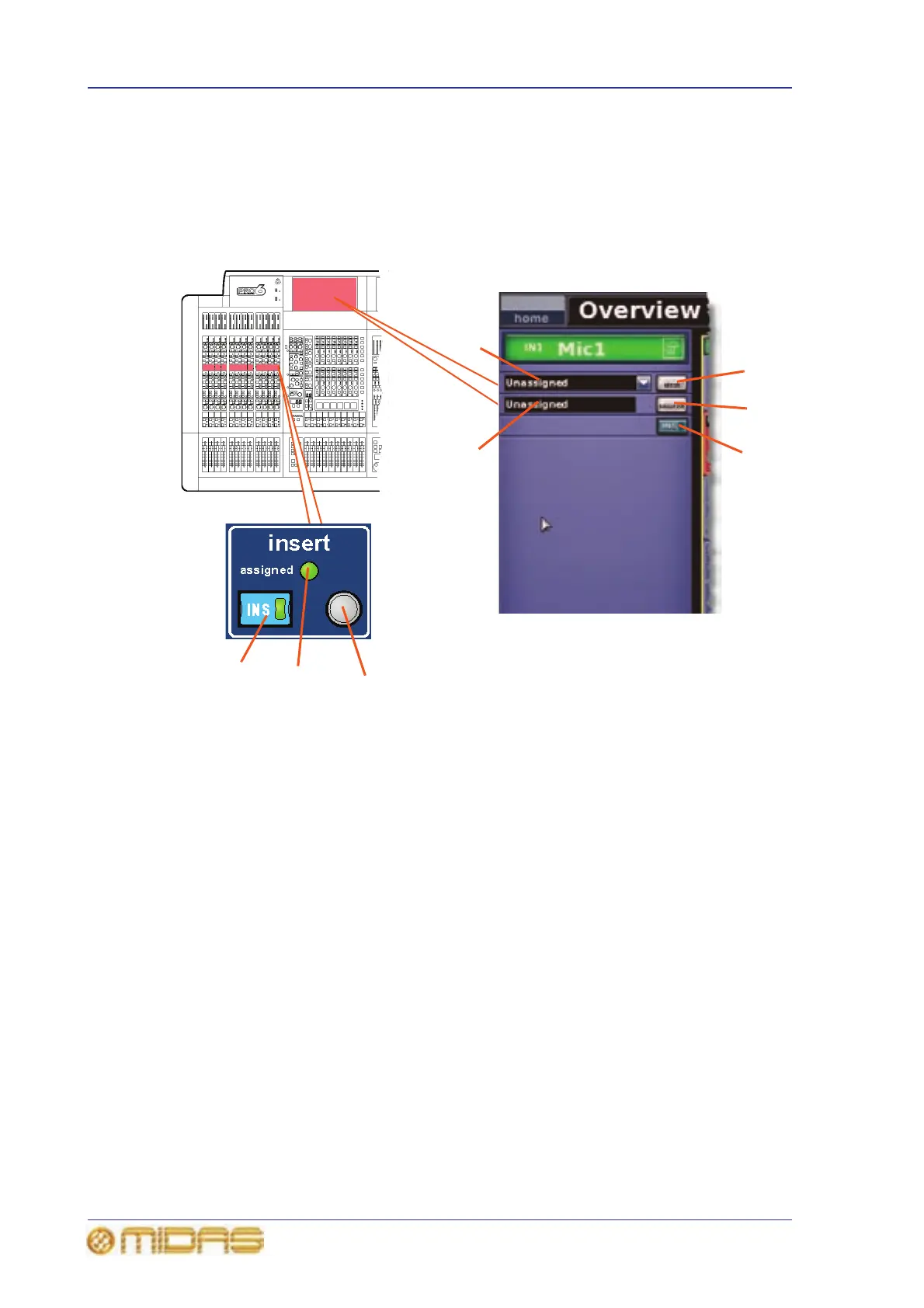
1 INS switch, connects (inserts) returned
programme material to the channel signal
path, provided both the insert send and insert
return points haves been assigned.
2 insert return field, shows you the source
of the insert return.
3 insert send field, has a drop-down list,
which shows the destination(s) of the insert
send.
4 Quick access button, selects the local
input channel and assigns the channel’s insert
processing area to the GUI channel strip.
5 Green assign LED, illuminates to show
that an insert return point is patched.
6 dest button, opens the Patching screen
from where you can select the destination of
the insert send.
7 source button, opens the Patching
screen from where you can select the source of
the insert return.
3
2
6
7
1
 Loading...