18 Chapter 3: About The PRO6 Control Centre
PRO6 Live Audio System
Owner’s Manual
Multiple hardware fault types are tolerated by the PRO6 Control Centre without loss of
audio control due to the dual redundancy and N+1 methods incorporated in the system.
This is further helped by the modular nature of the bays and GUI independence. Either
of the GUI screens can be used to operate the whole PRO6 Control Centre, even if none
of the control surface hardware is working. The unit offers the facility of universal
input, N+1 redundant power supplies with three latching mains connectors.
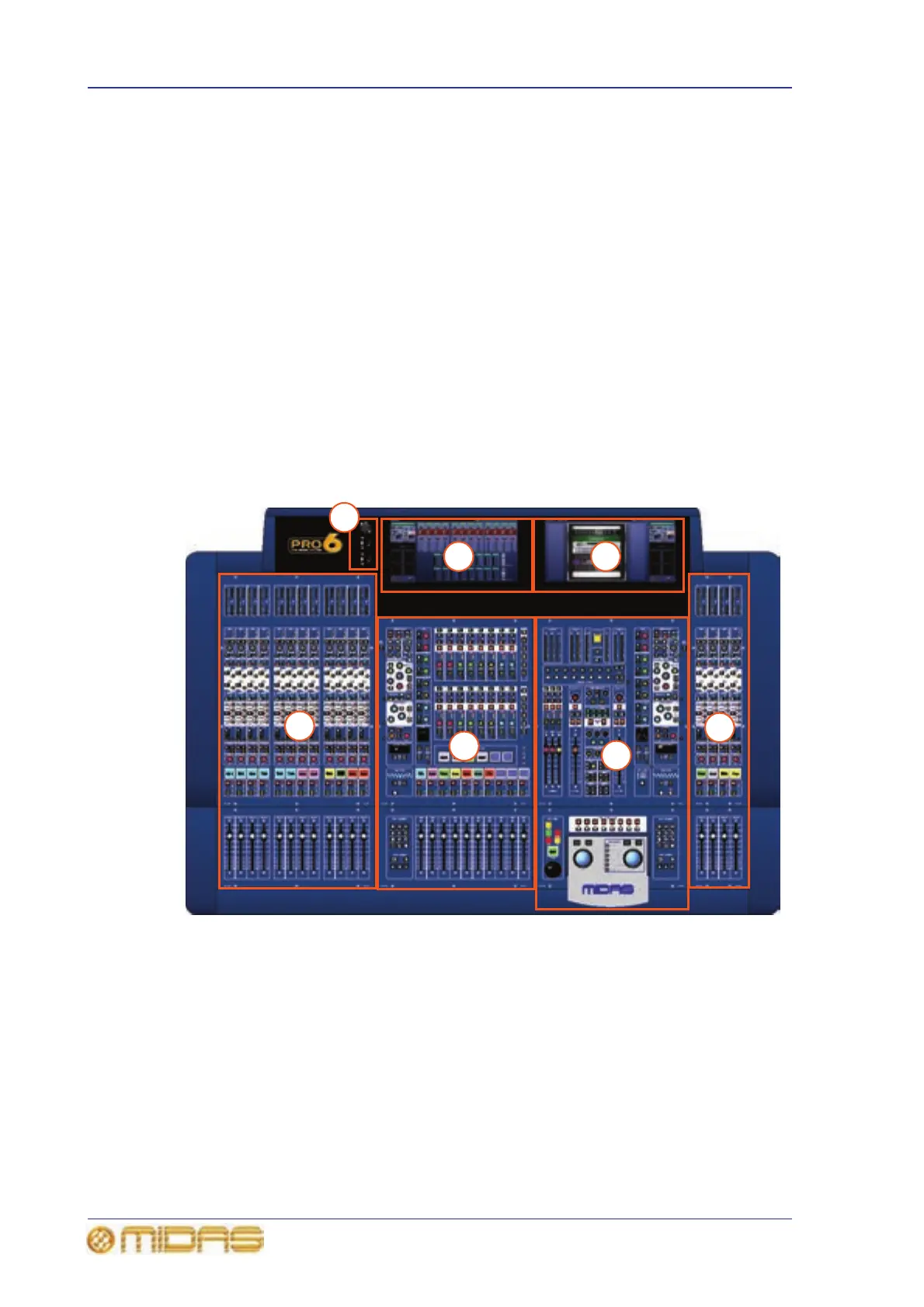
Bay and GUI layout
The PRO6 Control Centre has four discrete bays that house the following control surface
controls:
• Input bays (12-channel and 4-channel) — two input bays provide fast access to
input faders and important signal processing controls.
• Mix bay — provides access to outputs and groups, a detailed processing controller
(all channels) and navigational controls.
• Master bay — provides access to the master output mixes, monitor (A and B)
faders, automation, comms control, assignable effects control, and another set of
detailed processing and navigational controls.
Figure 1: Bay and GUI layout
Two GUI display screens at the top of the central bays provide extensive screen support
(standard configuration) and extra functionality for the channels and buses. For
example, when mixing or processing. They also facilitate the use of the GUI menu,
which gives you access to the many powerful features of the PRO6, such as patching,
effects, GEQs, diagnostics etc.
6
1
2
5
3
4
1 Input bay (12-channel).
2 Mix bay.
3 Master bay.
4 Input bay (4-channel).
5 Mix bay GUI screen.
6 Master bay GUI screen.
7 Talk mic and USB
connectors.
7
 Loading...