40 Chapter 6: Working With The PRO6 Control Centre
PRO6 Live Audio System
Owner’s Manual
About channel operation
During normal operation the task of controlling the input (12 channels), aux, return and
matrix channels is allocated to the two bays on the left. The two bays on the right
control the input (4-channel) and master channels.
This task allocation applies similarly to the GUI screens. However, you can control any
channel from either GUI screen. This is done by navigating the channel to the GUI
channel strip via the GUI menu; control is also then available via the local channel strip
on the control surface.
About GUI operation
This section explains the basic procedures you can perform at the GUI screens. In
general, you will control and operate the GUI by combining the operations described
here.
The GUI is not just an additional feature that enhances control surface operation, it is a
fully-featured tool in its own right. Not only does it show what is happening on the
control surface, but all of its controls are functional. The GUI contains most of the
controls found on the control surface and, in addition, has features that allow
configuration of the PRO6 and provide extra functionality.
The GUI is operated via the primary navigation zone and is principally the same as
using a laptop PC, although you can operate either screen using an external USB mouse
instead (see “Using an external USB mouse” on page 323). A USB keyboard is plugged
into the PRO6 for text editing.
LED Show status indication. An illuminated LED shows an
active (on) or enabled condition and, when
extinguished, it indicates an off or disabled condition.
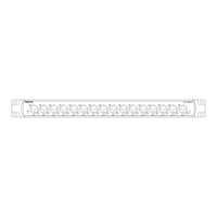
Meter All of the input fast strips, master fast strips and
monitors have a peak level meter. There are also
ones for the centre speaker and subwoofer of the 5.1
surround panning. In addition, each input fast strip
has a gain reduction meter for both the compressor
and gate.
Meters are included on a number of the GUI screens.
The ‘all meters’ display of the master bay’s default
GUI screen (see Figure 20, “Layout of the GUI
screens,” on page 116) provides an overview of what
is happening in the PRO6 by displaying meters for all
of the channels (inputs, outputs, monitors etc.).
Type Description Example(s)
 Loading...