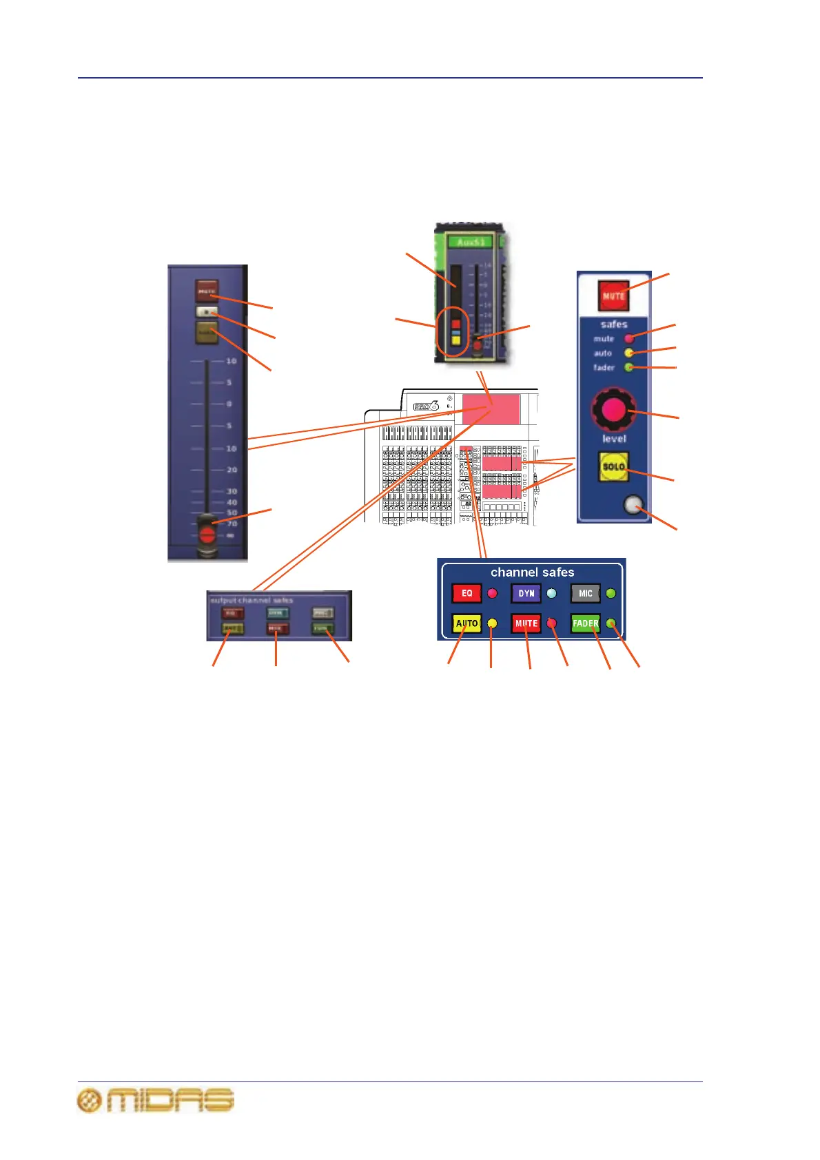
and output signal level control. This is supported on the GUI in the appropriate
processing area. In addition, the channel strips (control surface and GUI) have the full
complement of safes.
GUI channel strip
1 MUTE switch, mutes all post-processing
signals leaving the channel. (In addition to
scene recall, muting can be remote from the
auto-mute masters.)
2 Safe LEDs, illuminate when their
associated safe is on.
3 level control knob, adjusts the output
signal level. In the masters section (master
bay), this is a fader.
4 SOLO switch, activates signal routing to
the monitor A section of the control centre.
5 Quick access button, selects local output
channel and assigns the mute, level and solo
processing to the GUI channel strip.
6 FADER/[FDR] switch, switches fader safe
on so that the fader is removed from scene
recall.
7 MUTE/[MTE] switch, switches mute safe
on so that mute is removed from the scene
recall and auto-mute action.
8 AUTO/[AUT] switch, switches auto safe
on so that the channel is removed from scene
recall (this does not affect the action of the
auto-mutes and VCA control groups) and
control is removed from VCA control group
faders.
9 Fader for adjusting output signal level.
Has the same function as the level control
knob (see item 3).
10 Solo B switch (GUI only), changes the
operation of the SOLO switch so that it routes
signals to the Monitor B section of the control
centre.
11 Signal level meter.
12 Mute (red), solo B (blue) and solo (yellow)
on/off indicators.
1
2
2
2
3
4
5
1
10
4
9
6
7
8
6
7
8
2
2
2
Mute, solo and fader
processing area
GUI output fast strip
12
11
9
 Loading...