Home
Mindray
Diagnostic Equipment
Eagus R9
Mindray Eagus R9 User Manual
4
of 1
of 1 rating
365 pages
Give review
Manual
Specs
To Next Page
To Next Page
To Previous Page
To Previous Page
Loading...
S
truc
ture
an
d Ass
emb
ly/Di
sassemb
ly
9-
41
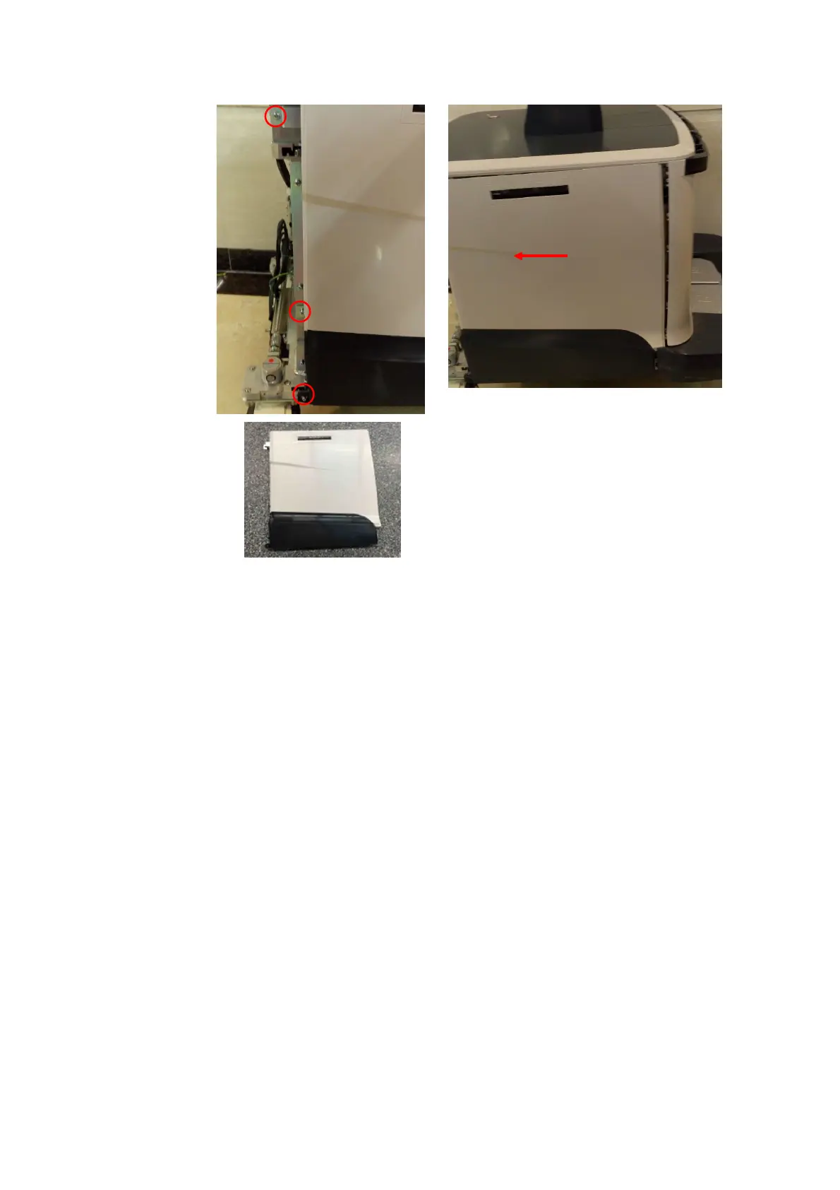
9.3.
18
Main
Unit
Right
Cover
A
s
sembly
Th
e
disas
sem
bly tool
: cros
s
-
hea
ded scr
ew
driv
er (M
3
, M
4).
1.
See
9.
3.1
6
for
det
ai
ls.
2.
U
nscr
e
w
3 M4 X
12 cros
s panhead s
crew
s
on the ri
ght
c
over
w
it
h sc
re
w
d
rive
r (M3,
M4) t
o
rem
ov
e the ri
ght
c
ov
er
of t
he
m
ain uni
t.
Mai
n
unit l
eft cov
er as
semb
ly
202
204
Table of Contents
Table of Contents
3
Revision History
9
Intellectual Property Statement
10
Applicable for
10
Statement
10
Responsibility on the Manufacturer Party
11
Service Contact
11
Safety Precautions
13
Meaning of Signal Words
13
Symbols
13
Meaning of Safety Symbols
13
Warning Labels
14
General Symbols
14
Safety Precautions
16
Electric Safety
16
Mechanical Safety
17
Personnel Safety
17
Other
17
Specifications
19
Overview
19
Intended Use
19
Introduction of each Unit
19
Peripherals Supported
28
Specifications
28
Dimensions & Weight
28
Electrical Specifications
28
Environmental Conditions
29
Monitor Specification
29
System Installation
31
Preparations for Installation
31
Electrical Requirements
31
Installation Conditions
32
Confirmation before Installation
33
Unpacking
33
Unpacking Process
33
Checking
36
Bare Machine Transport
37
Tool
37
Device Transport
38
Fixing Methods
38
Installing Main Unit
41
Opening up the Monitor
41
Connecting the Power Cord
41
Connecting ECG
42
Installing Probe Holder
42
Installing Gel Holder
42
Connecting the Transducer
44
Installing Peripherals
45
Connecting a Footswitch
45
Installing a Graph/Text Printer
45
Installing a Video Printer
48
Installing a Wireless Printer
49
Installing the Printer Driver in Windows Interface
49
Installing a Barcode Scanner
51
Ascending/Descending the Main Control Panel Manually
52
System Configuration
55
Running the System
55
Entering Doppler
55
System Preset
56
Printer Preset
57
Network Preset
58
Network Configuration
59
DICOM/HL7 Preset
62
Security
64
Check System Information
65
Product Principle
67
General Structure of Hardware System
67
Ultrasound Front Unit
68
Probe Board
69
TR Board
70
Engine Board
71
ECG Module
72
TEE Board
73
Ultrasound Back-End Unit
73
COME (CPU) Module
74
Independent GPU (GPU)
74
Memory Device (SSD&SATA Hard Disk)
74
PC Carrier Board
74
User I/O Interface Board
82
Wifi Module
83
Power Supply Unit
83
AC Interface Module
83
Auxiliary Output Power Isolation Transformer
84
AC-DC Module
84
DC-DC Board
84
PHV Module
84
Battery Management Board and Battery Module
85
New Power Supply Unit
86
AC-DC Module
87
To 24V Control Board
87
DC-DC Board
87
PHV Module
87
Battery Module
87
User Interaction Unit
87
Control Panel
87
Primary Display Assembly
88
Secondary Display Assembly
88
Electrical Ascending/Descending and Electromagnet
89
Function and Performance Checking Method
91
Note
91
Device Status Checking
91
Running Status
91
Working Condition
91
General Exam
92
Check Flow
92
Checking Content
92
Function Checking
94
Check Flow
95
Performance Test
101
Test Process
101
Test Content
101
Software Installation &Maintenance
109
Entering Maintenance
109
Set Installment
109
Software Installation/Restoration
112
Enter Windows
112
Software Maintenance
113
Export Log
113
Log Manager
113
Activating Operating System
115
Data Backup and Storage
118
Preset Data Management
118
Patient Data Backup and Restoration
119
Probe Check
119
Introduction on Hard Disk's Partitions
120
Adjustments
121
Adjusting Monitor
121
Adjusting Position
121
Adjusting Brightness and Contrast
124
Monitor Test
125
Touch Screen Adjustment
126
Touch Screen Brightness and Contrast Adjustment
126
Touch Screen Test
126
Control Panel Adjustment
127
Adjusting Caster
127
Field Replaceable Unit
129
Explosive View
130
Assembly Explosive View
131
Monitor Assembly (A0)
131
Monitor Support Arm Assembly (B0)
134
Main Control Panel Assembly (C0)
136
Control Panel Support Arm Assembly (D0)
144
Main Unit Assembly (E0)
147
Base Assembly (F0)
154
Base Power Box Assembly (G0)
155
Cable (H0)
157
Fusion Imaging Assembly (I0)
160
Structure and Assembly/Disassembly
163
Structure of the Complete System
163
Preparation
164
Tools Required
164
Engineers Required
164
Requirements
164
Assembly/Disassembly
165
Large/Small Probe Holders, Left Bracket of Coupling Gel Heating Cup, Intracavitary Probe Holder
167
Cup Rack Assembly
168
Wire Pothook Assembly
168
Mesh of the Base
169
Display (Monitor) Assembly
169
Control Panel Assembly
171
Handle Panel Assembly
182
Touch Screen Assembly
183
Speaker Cover Assembly
184
Left/Right Speaker Assembly
185
Upper/Lower Support Arm Cover
185
Support Arm Assembly
186
LCD Signal Connector PCBA Assembly
193
Control Panel Moving Mechanism Assembly
197
Main Unit Rear Cover Assembly
201
Main Unit Left Cover Assembly
202
Main Unit Right Cover Assembly
203
Main Unit Front-Top Cover Assembly
204
Turbine Cover
205
Turbine Protective Shell Assembly
205
Main Unit Top Cover/Main Unit Top Cover Assembly
206
Right/Left Brake Pedal
207
Machine Assembly
208
PC Main Board Assembly
215
Wireless Net Adapter
219
Antenna and Cable Assembly
220
Battery Assembly
221
IO Assembly
222
Probe Board Assembly
222
Electronics Assembly on the Base
223
HDD Assembly
231
DVD Assembly
232
Front Output Panel
234
ECG Assembly
236
Signal Cable of ECG Module
236
Mother Board Assembly
237
Housing Assembly of the Main Unit
240
Magnetic Generator Trolley
256
Magnetic Navigator
259
Installing Options
265
Installing Optional Software
265
Installation of Hardware Optional Function
267
Magnetic Transmitter Trolley Assembly
268
Probe Adapter Installation
270
Pencil Probe Signal Cable Assembly
271
Iclear Dongle
273
System Diagnosis and Support
275
General Status Indicator
275
Indicators on Control Panel
275
Display Status Indicator
276
Status of Entire Device
276
Starting Process of the Whole Machine
278
Alarming and Errors
279
The Voltage of System Power Is Abnormal
279
Abnormal Temperature
279
Battery Error
280
Fan Error
280
PHV Error
280
Board Error
281
Other Errors
281
Error Code List
282
Self Test
287
Self Test Introduction
287
Operation Procedures of Maintenance Self Test
287
User Self Test
292
Test Report
294
Care and Maintenance
297
Overview
297
Tools, Measurement Devices and Consumables
297
Routine Maintenance Items
297
Cleaning
299
System Cleaning
299
Peripherals Cleaning
303
Check
304
General Check
304
System Performance Check
304
Check for Peripherals and Optional Functions
305
Mechanical Safety Inspection
306
Electrical Safety Inspection
308
Troubleshooting of Regular Malfunctions
309
System Cannot Power on
309
Related Modules or Boards
309
Key Points Supporting Troubleshooting
309
Troubleshooting
310
System Cannot Start
311
Related Modules or Boards
311
Key Points Supporting Troubleshooting
311
Troubleshooting-The System Cannot Start
311
Image Problems
312
Related Modules or Boards
312
Key Points Supporting Troubleshooting
312
Troubleshooting-Imaging
313
Probe Socket System Malfunction
314
Related Modules or Boards
314
Key Points Supporting Troubleshooting
314
Troubleshooting of Probe Socket System
314
IO Interface System Failure
314
Key Points Supporting Troubleshooting
315
Troubleshooting of IO Interface System
316
Control Panel Failure
317
Related Modules or Boards
317
Key Points Supporting Troubleshooting
317
Troubleshooting of Control Panel
317
LCD Display Failure
318
Related Modules or Boards
318
Key Points Supporting Troubleshooting
318
Troubleshooting of the Monitor
319
ECG Module Failure
319
Related Modules or Boards
319
Key Points Supporting Troubleshooting
320
Troubleshooting for ECG Module
320
Troubleshooting
320
Related Modules or Boards
320
Drive Troubleshooting
320
Appendix A Electrical Safety Inspection
323
Appendix B Phantom Usage Illustration
341
Appendix C Description of Self Test Items
343
4
Based on 1 rating
Ask a question
Give review
Questions and Answers:
Need help?
Do you have a question about the Mindray Eagus R9 and is the answer not in the manual?
Ask a question
Mindray Eagus R9 Specifications
General
Brand
Mindray
Model
Eagus R9
Category
Diagnostic Equipment
Language
English
Related product manuals
Mindray Resona R9 Exp
492 pages
Mindray Resona R9
492 pages
Mindray Nuewa R9 Elite
365 pages
Mindray DC-80 EXP
383 pages
Mindray Z60
259 pages
Mindray MX7
338 pages
Mindray ME7
338 pages
Mindray DC-88
391 pages
Mindray DP-18
129 pages
Mindray TEX20
445 pages
Mindray Zonare ZS3
165 pages
Mindray Anesus Zeus
338 pages
 Loading...