Product Principle 4-3
4.2.1 Probe Board
Moth
er
boar
d
CPLD
POUT
switch
array
(relay)
Prb Con
A
Prb Con
B
Prb Con
C
Prb Con
D
POUT
x256
POUT
x256
POUT
x256
POUT
x256
ID_SPI
Probe control x4
Interrupt PRT_INT
TR board
xN
Control
JTAG
4D probe
control
selection
4D signal
Control
4D drive
module
4D signal
Control
192/TEE/DP special probe control
BTB connectionBTB connection
Probe
board
Power
supply
DSP
FPGA
Engine
board
EMIT[1-256]
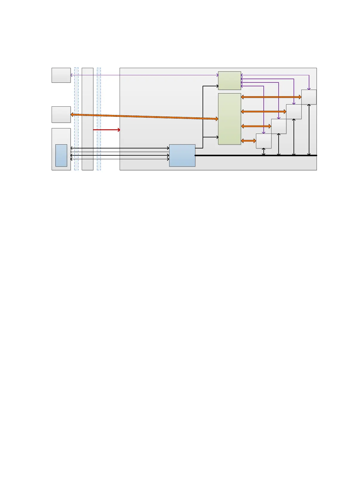
Figure 3 Schematic Diagram of the Probe Board
The hardware structure of the probe board is shown in the figure above: The introduction of probe
board is described as follows:
The probe board supports probe switching of four 408pin probe plug, every plug has 192-array
connecting with the main unit physical channels.
408-pin probe plug supports general probe (192-array at most), mechanical 4D, 1.25D/1.5D
probe, bi-plane, TEE (compatible with the interface) probe and probe containing high-voltage
switch.
Probe board FPGA supports on-line upgrade.
Support the detection of the probe’s hot swapping.
Support activating the indicator of the probe.
The probe board can be used for the burn-in without disassembling the JTAG of FPGA.
 Loading...