System Installation 3-15
3. Place the probe properly to avoid being treaded or wrapping with other devices (use
hanger or hook). DO NOT allow the probe head to hang free.
4. Turn the lock handle 90° anticlockwise to unlock it, and then pull out the connector.
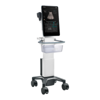
3.5 Installing Peripherals
For the models of the supported peripherals, please refer to “2.1.3 Peripherals
Supported”.
3.5.1 Connecting a Footswitch
Do not connect two or more footswitches to the main unit;
otherwise, it may lead to the malfunction to the system.
The system supports the wired footswitch (two-pedal, and three-pedal).
The setting for the wired footswitch:
1. Connection: directly insert the USB port of the footswitch to the system
applicable USB ports.
2. Function setting: for details, please refer to chapter 3.8.3.
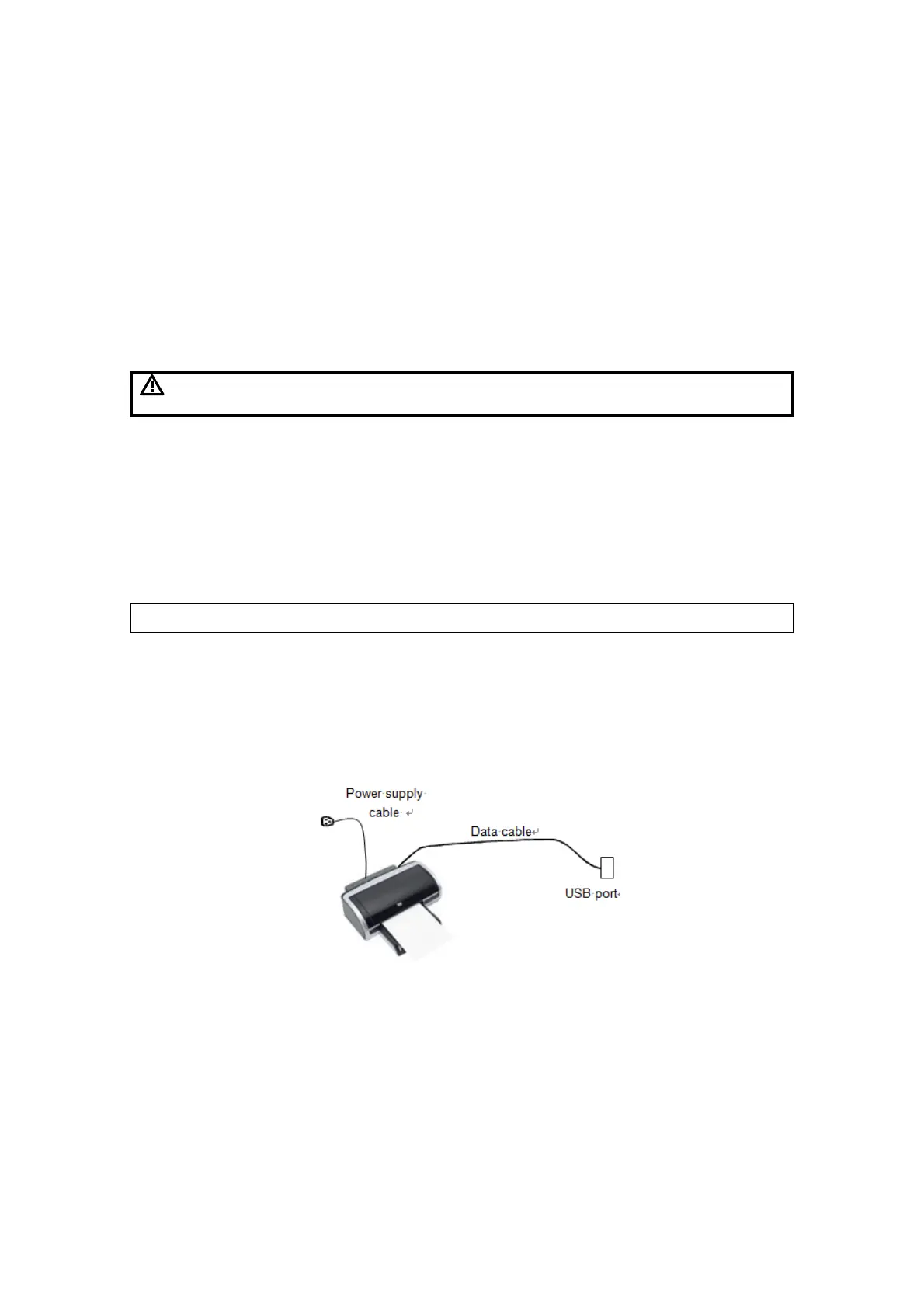
3.5.2 Installing a Graph/Text Printer
Please restart the ultrasound system after printer installation.
Connecting a local printer
NOTE: Unless otherwise specified, printers listed in “2.1.3 Peripherals Supported”
Chapter have drivers installed already.
As shown in the figure below, a graph / text printer has a power cord and data cable.
The power cord should be directly plugged into a well-grounded outlet.
1. Connect the data cable to the USB port on the ultrasound system.
2. Power the system and the printer on.
3. Put the installation optical disk of the printer driver into the DVD R/W drive.
4. Install the printer driver: Select [Setup]→[Print Preset]→[Add Printer].
 Loading...