4-2 Product Principle
4.2 Ultrasound Front Unit
TR
FPGA
DSP
FPGA
4D&TEE
Board
Pen Probe Conn
Engine Brd
TR_A Board
Clock
TR
FPGA
TR_B Board
TR_C Board
DataDataData
DDR
ATGC
Probe Various Signals
Probe Manager
Probe
Signal
Switch
Prb Con A
POUT(64)
Present/ID
Probe Board
POUT(64) POUT(64)
Probe Manager Communication
TX/RX
TX/RX
TX
RX
TX
RX
Physiological Signal
Module
Communication
Communication
Prb Con B
Prb Con C
Prb Con D
CTRL CTRLCTRL
CW
Mini Brd
TR
FPGA
TX
RX
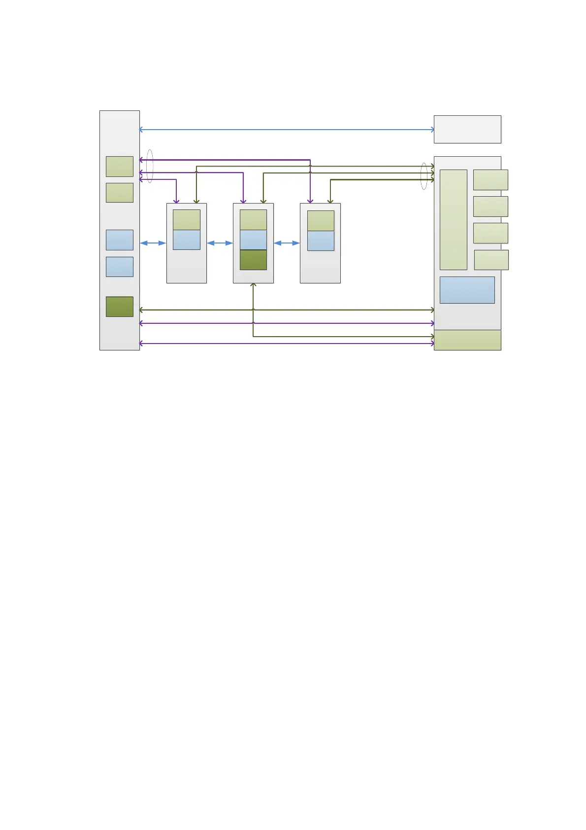
Fig 2 Schematic Diagram of Ultrasound System Front-end
Front-end unit mainly consists of:
Probe board
TR_A board, TR_B board, TR_C board
Engine board
CW sub-board (option configuration on the TR_A and TR_C board, standard configuration on
the TR_B board)
4D-TEE board
ECG module
Pencil probe board (optional)
Ultrasound front-end unit carries out the transmitting and receiving, the ultrasound image
signal will be sent to the CPU module on the digital board for post processing after amplification,
A/D conversion, beam forming and signal processing.
For details of the each board, see the following chapters:
 Loading...