Product Principle 4-19
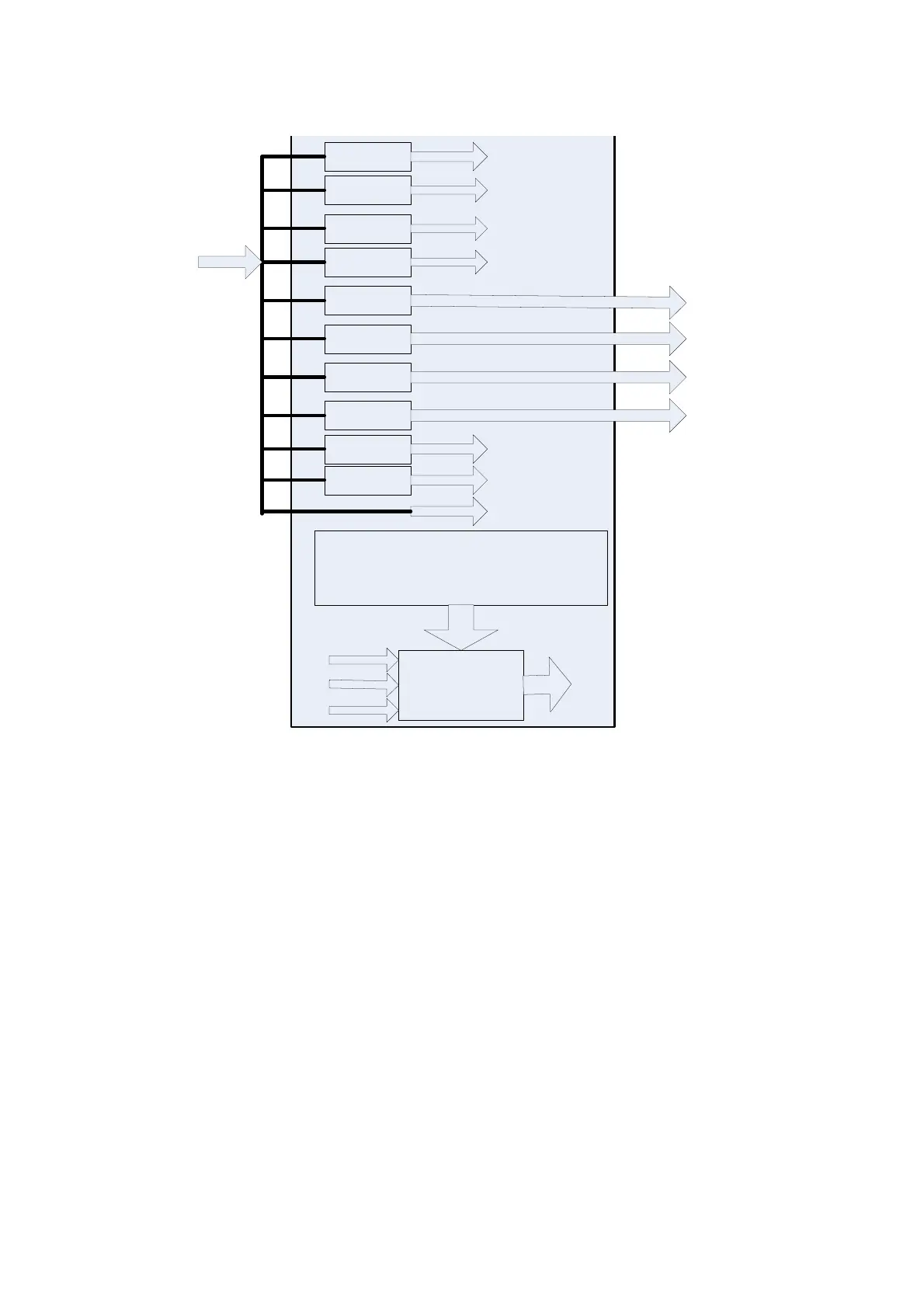
The PHV board functional block diagram is shown in the figure below:
Programmable
high-voltage
Programmable
high-voltage
Programmable
high-voltage
Programmable
high-voltage
High-voltage circuit
Flyback circuit
(programmable)
BUCK-BOOST circuit
(programmable)
BUCK circuit
(programmable)
ARM(ADUC7024)
function: monitor the output voltage, and make the
power supply programmable
PHV1PIN(10-110V)
PHV1NIN(10-110V)
PHV2PIN(10-110V)
PHV2NIN(10-110V)
HWP/N_Switch(+-100V)
BIAS(40-250V)
CWN
CWP
12VDC INPUT
DAC
signal
DAC clip
+
12VCC
+
3.3VCC
-12VCC
Programma
ble CNTR
BUCK
-BOOST
circuit
LDO
-12VCC
+3.3VCC
+12VCC
Supply the
power to the
internal clip
Figure 15 Schematic Diagram of PHV Board
4.4.6 Battery Management Board and Battery Module
The battery management board and the battery module are used for keeping the ultrasound system
on standby status after the AC power is disconnected. When the ultrasound system is on working
status, the battery is charged.
When the ultrasound system is on standby status and disconnected from AC power, the battery
provides 5V_Stb power for the ultrasound system to keep it on standby status.
The battery indicator is controlled by the battery management board and the battery module.
The design diagram of battery management board is shown as follows.
 Loading...