107Service Manual – SC5000 24 - Electrical System
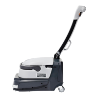
The main electrical bay is located below the
operator’s seat, behind a removable panel. This
contains the Main Machine Controller, the Drive
Controller, and the Power Module. The K2 Relay
provides high-energy power to the power module,
and is controlled by the power module itself.
One side of the K2 power relay coil is connected
to battery power, and the Power Module
activates the relay by pulling the other
connection to ground.
Low Voltage Cutout
The main machine controller is equipped with a low-voltage cutout feature to prevent over-discharging of the
batteries. When the battery voltage falls below a dened threshold, some machine functions are disabled.
These threshold values are dependant on the type of battery specied in the main controller. In the rst
stage of cutout, the scrub system is disabled, but the recovery system will remain active. At the second stage,
even the recovery system will be disabled, but the drive system remains active.
The drive controller has its own cutback feature, separate from the main controller. When the drive
controller senses battery voltage too low, it will reduce power output to the drive motor to protect the
battery.
Cutout Level Threshold-Wet Threshold-AGM Affected Systems
Stage 1 30.8 32.6 All scrub functions disabled
Stage 2 30.6 32.4 Both scrub and recovery disabled
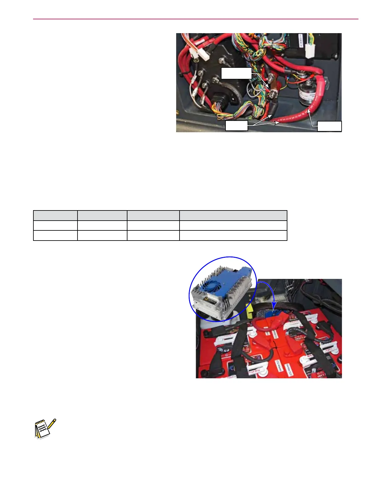
Onboard Battery Charger
An optional on-board battery charger is mounted
below the operator’s seat on the right side of the
batteries. The charger should be a Delta-Q model
RC1200. The charger is intelligent and semi-
autonomous and charges the batteries when the
machine is plugged in to facility power.
The charger communicates with the Main Machine
Controller (MMC) via the CAN-0 bus. The MMC tells
the charger which charging prole it should be using
based on the type of battery installed in the machine.
The charger can also communicate battery and
charger status back to the MMC.
To prevent any machine operation while the charger
is plugged in, the charger contains an interlock relay
which closes a circuit back to the MMC when ever
the charger is plugged in. During normal operation, the Interlock Return signal is open-circuited, which the
MMC detects as a low-voltage. When the charger is plugged in, the Interlock Return is connected to battery+
by the relay, and the MMC detects this as a high-voltage.
Note: If the battery charger is disconnected from the batteries, when it gets re-connected, it will not
have CANBus communication enabled. This will result in a controller error code of 1-058
for loss of communication. To reset communication, plug the charger into facility power (as
though charging the batteries) for 30 seconds.
K2 Power
Relay
Main
Ground Lug
Battery
Cables

 Loading...