Home
Nilfisk-Advance
Scrubber
Advance SC5000
Nilfisk-Advance Advance SC5000 Service Manual
5
of 1
of 1 rating
218 pages
Give review
Manual
Specs
To Next Page
To Next Page
To Previous Page
To Previous Page
Loading...
77
Service Manual – SC5000
14 - Wheel System, Non-T
raction
Functional Description
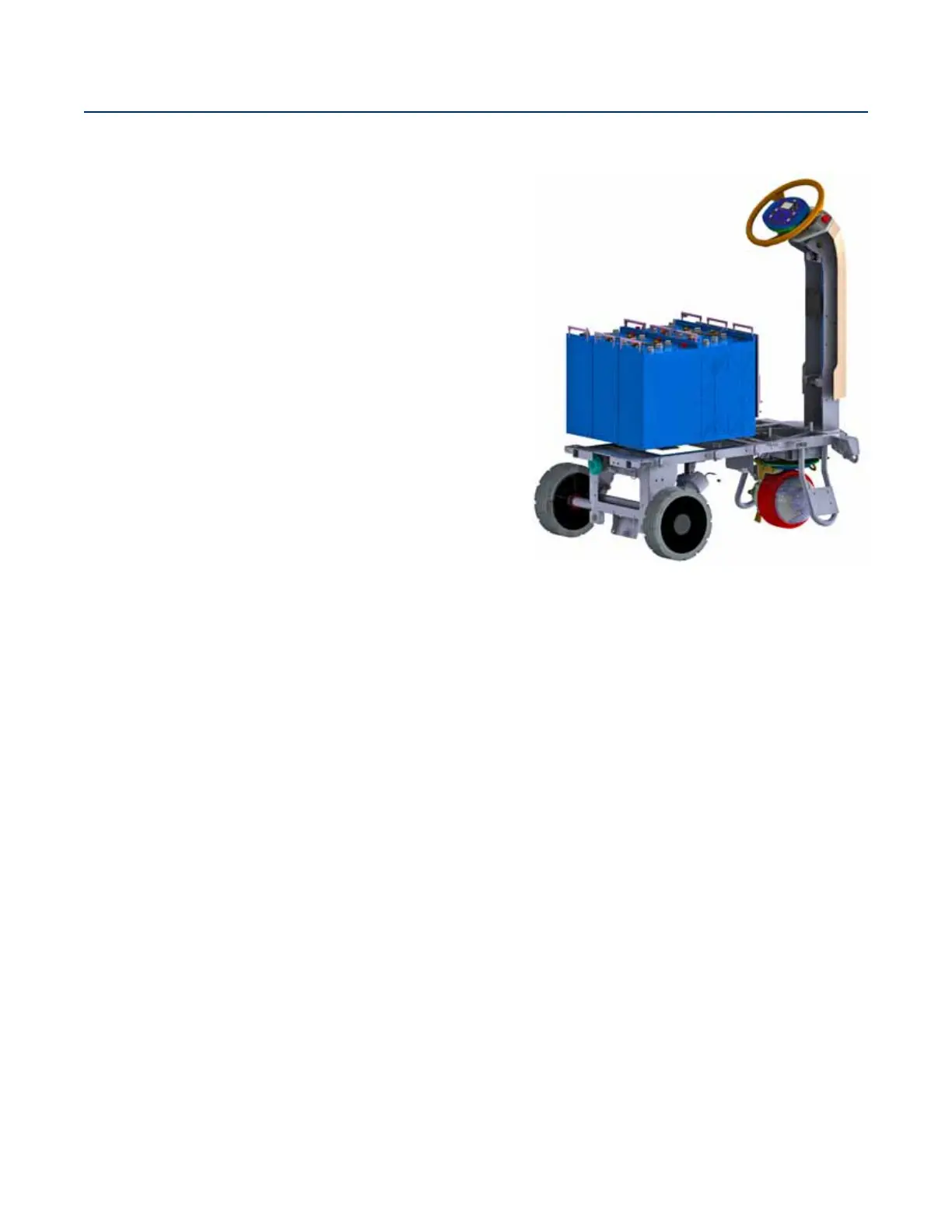
The non-traction wheels are intended to carry the majority
of the machine’s weight. The wheels are strategically located
below the battery compartment and between the recovery and
solution tanks. The non-traction wheels are mounted directly
to the machine’s subframe.
76
78
Table of Contents
Table of Contents
2
Sheet
2
03 - General Information
7
General Machine Description
7
Service Manual Purpose and Application
7
Other Reference Manuals and Information Sources
7
Revision Table
7
Parts and Service
8
Diagnostic and Service Tools
8
Conventions
8
Modifications
8
Nameplate
8
Safety
9
Symbols
9
General Safety Instructions
9
Transporting the Machine
11
Moving a Disabled Machine
11
Lifting the Machine
12
Technical Specifications
13
Fastener Torque Specifications
14
Maintenance Schedule
14
Maintenance Procedure References
15
Lubricate the Machine
15
Know Your Machine
16
Main Assemblies
16
Machine Components
17
Front RH View
17
Rear LH View
18
04 - Control System
19
Functional Description
19
Functional Diagram
20
Drive Controller
21
Power Module
22
Main Machine Controller
23
Main Controller Operational Modes
24
Operational Mode Prerequisites
24
Control Panel
26
CAN Bus Communication
27
Component Locations
28
Main Machine Controller Programming
29
Service Mode Access
29
Menu Navigation
29
Programming Menu Outline
30
Hours Menu
31
Faults Menu
31
Keys Menu
31
Authorizing User Keys
31
Deauthorizing User Keys
31
Service Menu
32
A1 Main Controller
32
A3 Power Module
33
A4 Drive Controller
34
Output Test
35
Deck Lift
35
Panel Test
36
Options Menu
36
Configuration Menu
37
System Menu
38
Impact Log
38
Troubleshooting
39
Main Controller (A1) Error Codes
41
Power Module (A2) Error Codes
49
User Interface (A9) Error Codes
68
Specifications
70
Sample Shop Voltage Measurements
70
Maintenance
74
Firmware Update
74
Removal and Installation
75
Main Machine Controller
75
14 - Wheel System, Non-Traction
77
Functional Description
77
Removal and Installation
78
Rear Wheel Bearings and Seal
78
Rear Brake Calipers
80
20 - Drive System
83
Functional Description
83
Drive Motor
83
Drive Pedal Potentiometer
83
Drive Controller
84
Operational Mode Prerequisites
85
Troubleshooting
85
Drive Controller (A4) Error Codes
85
Removal and Installation
92
Drive Controller
92
Drive Wheel Assembly
93
Electromechanical Brake
96
Drive Tire
97
Specifications
100
Sample Shop Voltage Measurements
100
22 - Steering System
101
Functional Description
101
Maintenance and Adjustment
102
Steering Chain Tension
102
Removal and Installation
103
Steering Column Covers
103
Steering Offset Box
104
24 - Electrical System
106
Functional Description
106
Low Voltage Cutout
107
Onboard Battery Charger
107
Component Locations
108
Troubleshooting
109
Battery Testing
109
Battery Charger Error Codes
110
Maintenance and Adjustment
120
Battery Settings
120
Onboard Battery Charger
120
Removal and Installation
121
Batteries
121
Wiring Diagrams
122
Understanding the Features of the Electrical Circuit Diagram
122
Device Labeling
123
Navigation
123
Electrical Circuit Diagram
124
Sheet 1, Contents
124
Sheet 2: Power/Charger/Main Controller Power
125
Sheet 3: Controller Power
126
Sheet 4: Main Controller Functions
127
Sheet 5: Power Module
128
Sheet 6: Drive Module
129
Sheet 7: Vehicle Circuits
130
Sheet 8: CAN Bus
131
Condensed Electrical Circuit Diagram
132
Sheet 1: Main Machine Controller
132
Sheet 2: Power Module
133
Sheet 3: Drive Controller
134
Using the Wiring Diagram
135
Wire Numbers
135
Splice Points
135
Connector Numbers
135
Wiring Diagram
136
Sheet 1
136
Appendix A: CAN Wiring
138
Appendix B: KSI Wiring
139
Harness Diagram
140
Sheet 1: Navigation
140
Sheet 2: Lower Elec Bay, Front Chassis
141
Sheet 3: Drive Controller, Traction Harness
142
Sheet 4: Main Controller, KSI Relay Areas
143
Sheet 5: Power Module, Machine Power
144
Sheet 6: Lower Chassis and Scrub Deck Areas
145
Sheet 7: Rear Chassis, Recovery, OBC, Column Harness
146
3D Harness Connector Diagrams
147
All Harnesses
147
Power Distribution
148
Main Harness, Electrical Bay
149
Column Harness and Main Harness-Front
150
Traction Harness
151
Main Harness, Rear
152
Electrical Connector Pin-Out Assignments
153
30 - Solution System
167
Functional Description
167
Shutoff Valve
167
Solution Solenoid
167
Solution Level Sensor
167
External Wash Options
168
Ecoflex Option
169
Plumbing Diagram
170
Operational Mode Prerequisites
170
Troubleshooting
171
Detergent Not Flowing
171
Solution Level Indication Is Not Correct
172
Testing Individual Sensor Bodies
172
Removal and Installation
174
Solution Solenoid
174
Detergent Pump
175
Wash Hose Pump (Option)
176
Specifications
177
34 - Scrub System, Disc
178
Functional Description
178
Deck Lift Actuator
178
Scrub Control
179
Operational Mode Prerequisites
179
Circuit Overview
180
Maintenance and Adjustment
181
Lift Actuator Limit Adjustment
181
Removal and Installation
183
Scrub Deck
183
Deck Lift Actuator
184
Brush Motor
184
Brush Motor Brushes
185
Specifications
187
Special Tools
187
Actuator Test Kit
187
34 - Scrub System, Cylindrical
188
Functional Description
188
Deck Lift Actuator
188
Scrub Control
189
Operational Mode Prerequisites
190
Circuit Overview
190
Maintenance and Adjustment
191
Lift Actuator Limit Adjustment
191
Removal and Installation
193
Scrub Deck
193
Deck Lift Actuator
195
Brush Drive Belt
196
Brush Motor
196
Brush Motor Brushes
198
Specifications
200
Special Tools
200
Actuator Test Kit
200
38 - Squeegee System
201
Functional Description
201
Squeegee Lift Actuator
201
Squeegee
202
Maintenance and Adjustment
202
Squeegee Blade Cleaning and Inspection
202
Squeegee Height and Tilt Adjustment
203
Squeegee Actuator Limit Adjustment
204
Removal and Installation
206
Squeegee Lift Actuator
206
Specifications
207
Special Tools
207
Actuator Test Kit
207
40 - Recovery System
208
Functional Description
208
Vacuum Motor and Recovery Tank
208
Operational Mode Prerequisites
208
Vacuum Motor Control Circuit Overview
209
Troubleshooting
210
Vacuum Suction Test
211
Removal and Installation
212
Recovery Tank
212
Vacuum Motor
212
Vacuum Motor Brushes
214
Specifications
215
Special Tools
215
90 - Options and Accessories
216
Beacon
216
Headlights
216
Blue Light
216
On Board Charger (OBC)
216
Ecoflex
216
Scrub-N-Vac
217
Wash Hose
217
Trackclean
217
Dual Vacuum
217
Side Sweep
217
Various Mechanical Kits
218
Other manuals for Nilfisk-Advance Advance SC5000
Instructions For Use
122 pages
5
Based on 1 rating
Ask a question
Give review
Questions and Answers:
Need help?
Do you have a question about the Nilfisk-Advance Advance SC5000 and is the answer not in the manual?
Ask a question
Nilfisk-Advance Advance SC5000 Specifications
General
Brand
Nilfisk-Advance
Model
Advance SC5000
Category
Scrubber
Language
English
Related product manuals
Nilfisk-Advance Advance SC400
2 pages
Nilfisk-Advance Advance SC250
68 pages
Nilfisk-Advance Advance SC1500
132 pages
Nilfisk-Advance Advance SC750 ST
133 pages
Advance SC901 ST-34D
74 pages
Advance SC900 ST-28D
24 pages
Advance Advenger 2800ST Series
124 pages
Nilfisk-Advance Adfinity 20D
124 pages
Nilfisk-Advance AquaRide SE
82 pages
Nilfisk-Advance SC6500 40C
213 pages
Nilfisk-Advance Liberty SC50
66 pages
Nilfisk-Advance 56315036(28D)
81 pages

 Loading...