70Service Manual – SC5000 04 - Control System
Specications
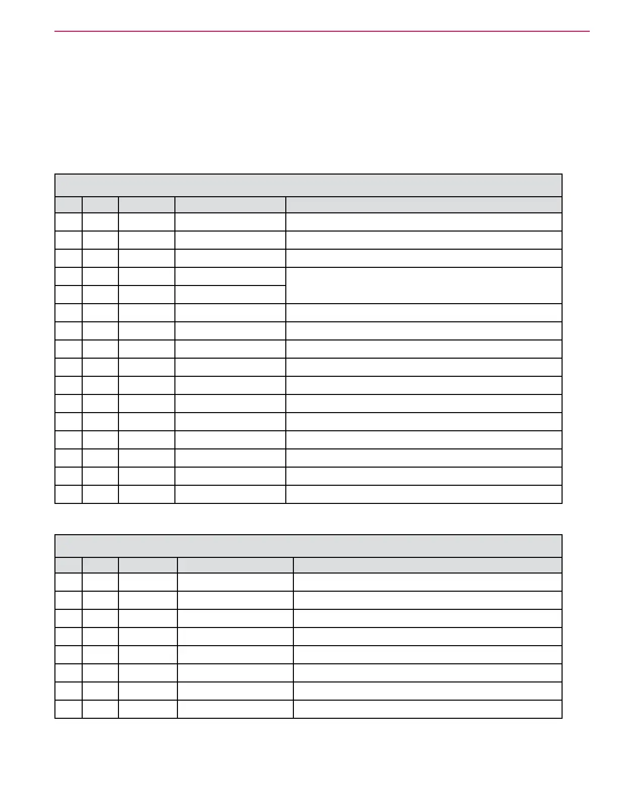
Sample Shop Voltage Measurements
The following tables contain some “real world” shop voltage measurements to help you recognize what
“normal” looks like. All voltage values were measured with the black (Negative) voltmeter lead connected to
the main battery negative unless otherwise specied. Most outputs were turned on using the Service/Output
test function. Machine battery voltage at time of testing was 37.25V.
J1 Main Machine Controller
Pin# Wire Color Function Observations
1 W102 GRY Ground
2
3
4 W152 BRN-GRY Detergent Pump Repeating pulse train Off/Pos//Neg/Off. Pulses too short for
accurate voltage measurement.
5 W151 BRN-RED Detergent Pump
6
7
8 W074 GRY-BLU Beacon Not Available
9 W102 GRY Ground Reference
10 W078 GRY-BLU Backup Alarm B+ = off, 0.01 = on
11 W082 GRY-BLU Horn B+ = off, 0.1 = on
12 W109 YEL KSI In B+
13 W109 YEL KSI In B+
14 W145 BLU-YEL Solution Solenoid B+ = off, 0.1 = on
15 W106 ORN-BRN KSI Coil Out 0.62 = on
16 W100 ORG Bat+ B+
J2 Main Machine Controller
Pin# Wire Color Function Observations
1
2
3 W115 BLU-YEL Solution Level +5V 5.0
4 W125 BRN Sweep Switch Not Available
5 W108 BLU-WHT Seat Switch Open = 0.2, Seated = B+
6 W030 GRN OBC Interlock Not Available
7 W107 GRY-BLU E-STOP Open = B+, Closed = 0.02
8

 Loading...