190Service Manual – SC5000 34 - Scrub System, Cylindrical
Operational Mode Prerequisites
Before the main controller can activate any of the operational modes, it must rst check that the appropriate
prerequisites are met.
• Scrub System Outputs
– Brush Motors (M1 and M2) or Deck Actuator (M7)
◦ Seat switch must be closed to enter scrub mode
◦ No scrub system fault (brush motors and actuator motor)
◦ No recovery system fault (vac motors and squeegee)
◦ Throttle command not equal to zero
◦ No Estop inhibit
◦ No impact lockout inhibit
◦ No low voltage cut out inhibit (rst or second stage)
◦ No RTF inhibit
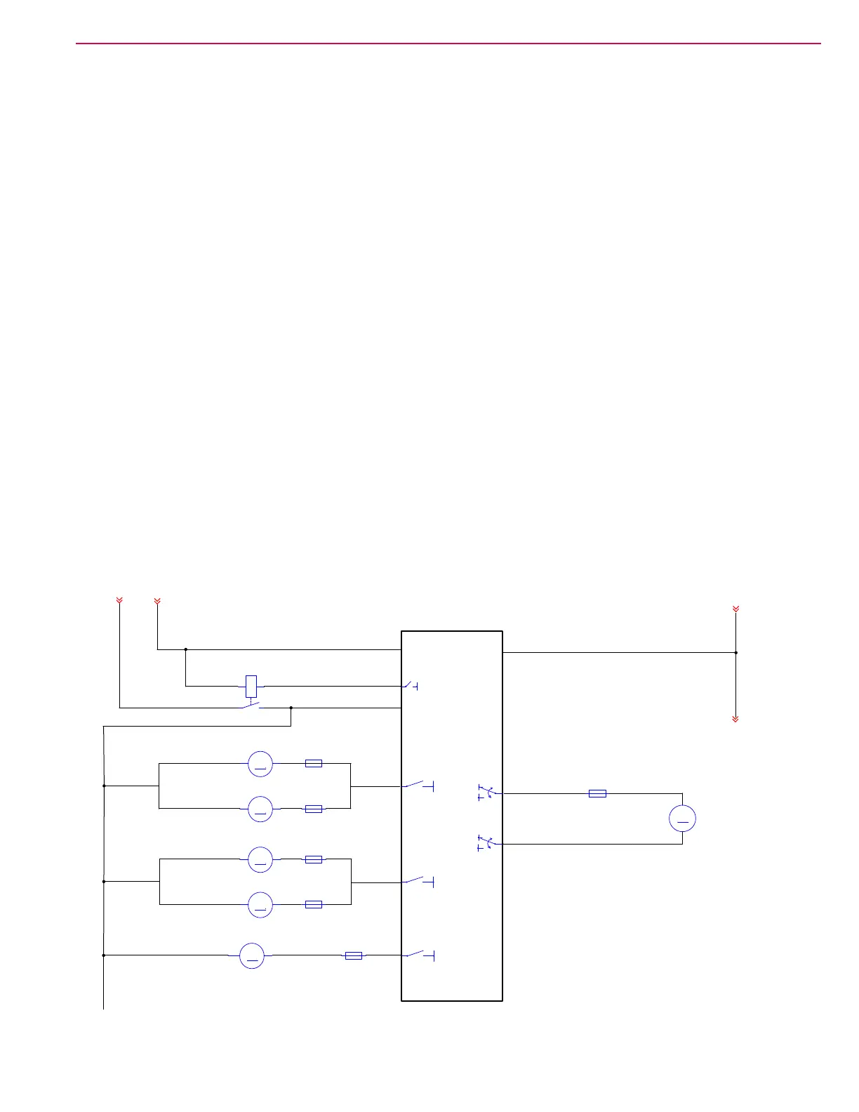
Circuit Overview
The brush motors are powered from the power module. The power module controls the K2 relay, which
provide battery+ power to the motors. The power module then applies PWM control to the negative side of
the motor, including soft-start at startup. The power module monitors the health and performance of the
motors and reports this information back to the main controller. The optional side sweep motor is controlled
in the same manner.
The deck lift actuator is powered from the power module, which needs to reverse the polarity to this motor in
order to raise and lower the deck in very small amounts to maintain pressure. The signal from the controller
is reversible Pulse-Width Modulated (PWM).
J6-6
J6-1
A2
POWER MODULE
M3
M2
M1
(OPTIONAL)
M7
BRN/GRY
BRN/RED
RED/WHT
WHT/GRY
BRN/GRY
RED/BRN
BRN/GRY
RED/BRN
-BV
+BV
M3
SIDE SWEEP
F3
FUSE, 30A.
1 2
F6
FUSE, 10A.
1 2
F12
FUSE, 40A.
1 2
F13
FUSE, 40A.
1 2
LEFT DISK
B-
B-
M
M7
DECK ACTUATOR
-
+
F10
FUSE, 10A.
1 2
REAR CYLINDERICAL
-BV
+BV
B-
F4
FUSE, 30A.
1 2
KSI
B+
B-
J3-2
J3-9
RED
BLK
RED
BRN
YEL
BATTERY +
BATTERY -
K2
POWER MODULE CONTACTOR
3 4
1
2
B-
KSI
OR
BRUSH MOTOR M2
RIGHT DISK
FRONT CYLINDERICAL
OR
BRUSH MOTOR M1
M
-+
M
-+
M
-+
M
-+
M
-+

 Loading...