22Service Manual – SC5000 04 - Control System
Power Module
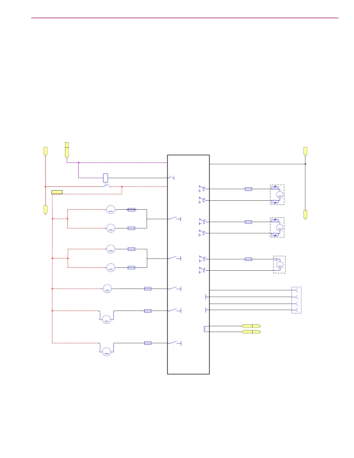
As the name suggests, the power module handles the high-power output functions for the machine. It
receives its commands from the main machine controller via the CAN Bus network. The power module
provides basic motor control and protection, but the main machine controller controls the actual operation
commands for the motors.
The power module receives its logic power from the KSI relay, which is controlled by the main machine
controller. The power module has control of its own high-power input from the K2 relay. Unlike the
drive module, the power module has no direct inhibit input signals (i.e. seat switch or E-stop), except by
commands on the CAN Bus.
The power module has 2 types of outputs. The higher power outputs are non-reversing PWM control. The
lower power outputs are reversing PWM control. The power module is capable of monitoring the output
amperage from each of the outputs, and reporting this information to the main machine controller via the
CAN Bus.
(Optional)
A2
POWER MODULE
(Optional)
(Optional)
M6
M7
M8
F6
Fuse, 25A.
M3
Side Sweep
F3
Fuse, 30A.
F8
Fuse, 10A.
M8
Wash Pump
F12
Fuse, 40A.
F11
Fuse, 40A.
Left Disk
M7
Deck Actuator
F7
Fuse, 5A.
F10
Fuse, 10A.
Rear Cylinderical
M5
Motor, Vacuum 2
F9
Fuse, 10A.
F5
Fuse, 25A.
M6
Squeegee
Actuator
M4
Motor, Vacuum 1
F4
Fuse, 30A.
K2
Power Module Contactor
Or
Brush Motor M2
Right Disk
Front Cylinderical
Or
Brush Motor M1
Serial Port
Programmer
Connector
M
+
−
M
+
−
M
+
−
M
12
M
12
M
+
−
M
+
−
M
+
−
M
+
−
M
+
−
1
2
3
4
15V
B-
TX
RX
CAN(1) L
CAN(1) H
120Ω
B-
B-
B-
B-
-BV
+BV
-BV
+BV
B-
KSI
B+
B-
B-
-BV
+BV
-BV
+BV
-BV
+BV
-BV
+BV
3 4
1
2
1 2
1 2
1 2
1 2
1 2
1 2
1 2
1 2
1 2
1 2
K2 Bat+
CAN1H MMC
CAN1L MMC
Batt- Batt-
BLU/RED
BLU/GRY
BRN/GRY
BRN/RED
GRN/WHT
GRN/RED
BRN/GRY
BRN/GRY
RED
BLK
BRN
YEL
BLK
RED
PNK/YEL
PNK/BRN
GRN/GRY
BRN/WHT
GRN/GRY
RED/GRN
RED/WHT
RED/GRN
RED/BRN
RED/BRN
RED
J6-14
J6-13
J6-6
J6-1
J6-10
J6-11
M4
M3
M5
M2
M1
J3-2
J6-7
J6-12
J6-8
J6-5
J6-3
J6-4
X225
J3-9
KSI MMC
Batt+ Batt+

 Loading...