167Service Manual – SC5000
30 - Solution System
Functional Description
The SC5000 solution tank is incorporated
directly into the main body of the machine. A
series of 3 capacitive sensors serves as a level
indicator for the amount of solution in the
tank. The outlet of the tank has a manual
shutoff valve so that components can be
serviced without solution owing out of the
tank. Just downstream from the shutoff is a
lter element to prevent debris from entering
other components of the system.
The supply hose leads to the scrub deck,
where the solution solenoid meters uid
delivery. The supply hose is a specially
molded tube that also contains ttings for
the optional EcoFlex detergent inlet and the
option pump outlet.
Shutoff Valve
A bidirectional shutoff valve permits the
solution ow to be shutoff, directed toward
the scrub deck, or directed toward the drain
hose. The ow is off when the handle is
perpendicular to the body. When the handle is parallel to the body, it could be pointed either way, so it is
best to conrm the desired position.
Solution Solenoid
The solution solenoid is located downstream from the solution lter, and activates to allow solution to
ow to the scrub deck. To prevent pooling of excess water on the oor when the machine is stationary, the
solenoid output from the controller is disabled when the wheel drive is not active. The rate of solution ow is
controlled by cycling the solution solenoid on and off at varying duty cycles.
Solution Level Sensor
The solution level sensor is comprised of 3 discrete sensor bodies
wired together to function as a single unit. The 3 sensor bodies are
located on the right-rear corner of the solution tank, with the lower
sensor (not visible) located just above the rear wheel.
The sensors operate by detecting the capacitance of the solution in
the solution tank. This capacitive detection is similar to how some
touch sensors work to detect a human touch. When the sensor’s
circuitry detects an increase in nearby capacitance, it activates
a transistor switch, which connects a 2k Ω resistor between the
positive and negative power terminals within the sensor.
The effect of switching this relatively small resistor into, and out of,
the circuit, causes the sensor to consume more, or less amperage,
which the Main Machine Controller can detect.
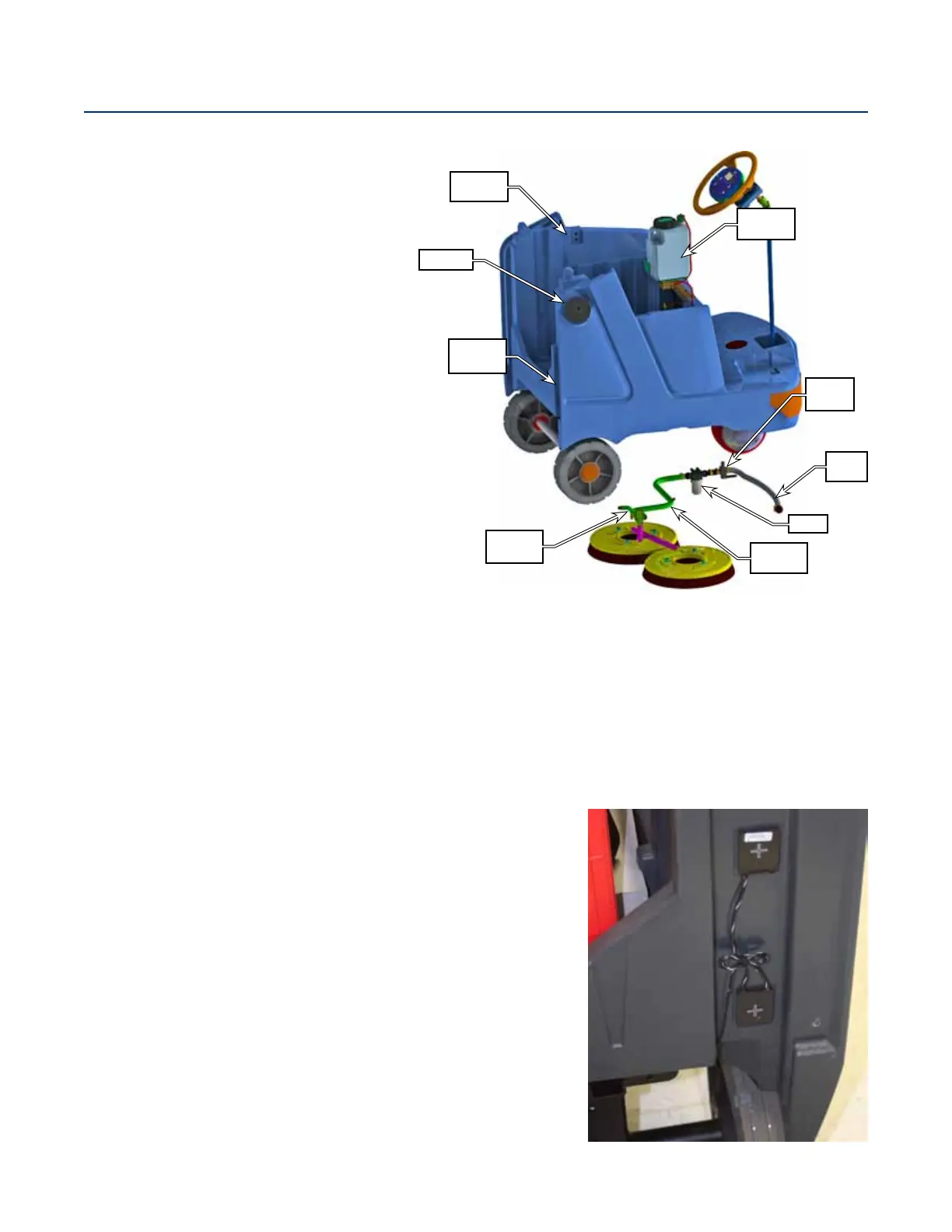
Level
Sensors
Fill Cap
Solution
Tank
Solution
Solenoid
Supply
Hose
Drain
Hose
Filter
Shutoff
Valve
EcoFlex
System

 Loading...