92Service Manual – SC5000 20 - Drive System
Removal and Installation
Drive Controller
WARNING: Disconnect the main battery connector before servicing
the drive controller. The drive controller has high-
amperage, unswitched battery power at its terminals.
1. Turn off the machine and disconnect the main
battery connector.
2. Remove the 4 screws that secure the electrical bay
cover, and remove the cover.
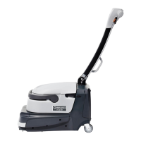
3. Disconnect the EM brake connector (J4) from the
drive controller.
4. Disconnect the logic cable connector (J5) from the
drive controller.
5. Disconnect the battery positive and negative
connections (Bat+, Bat-) from the drive controller.
6. Make sure the motor leads are labeled for
reassembly, and then disconnect the three motor leads (U, V, W).
Note: If any of the wires are reversed during replacement, the drive motor will rotate backward
and operate loudly as the motor windings conict with one another. The drive controller will
also likely issue an encoder fault because the encoder will provide unexpected results.
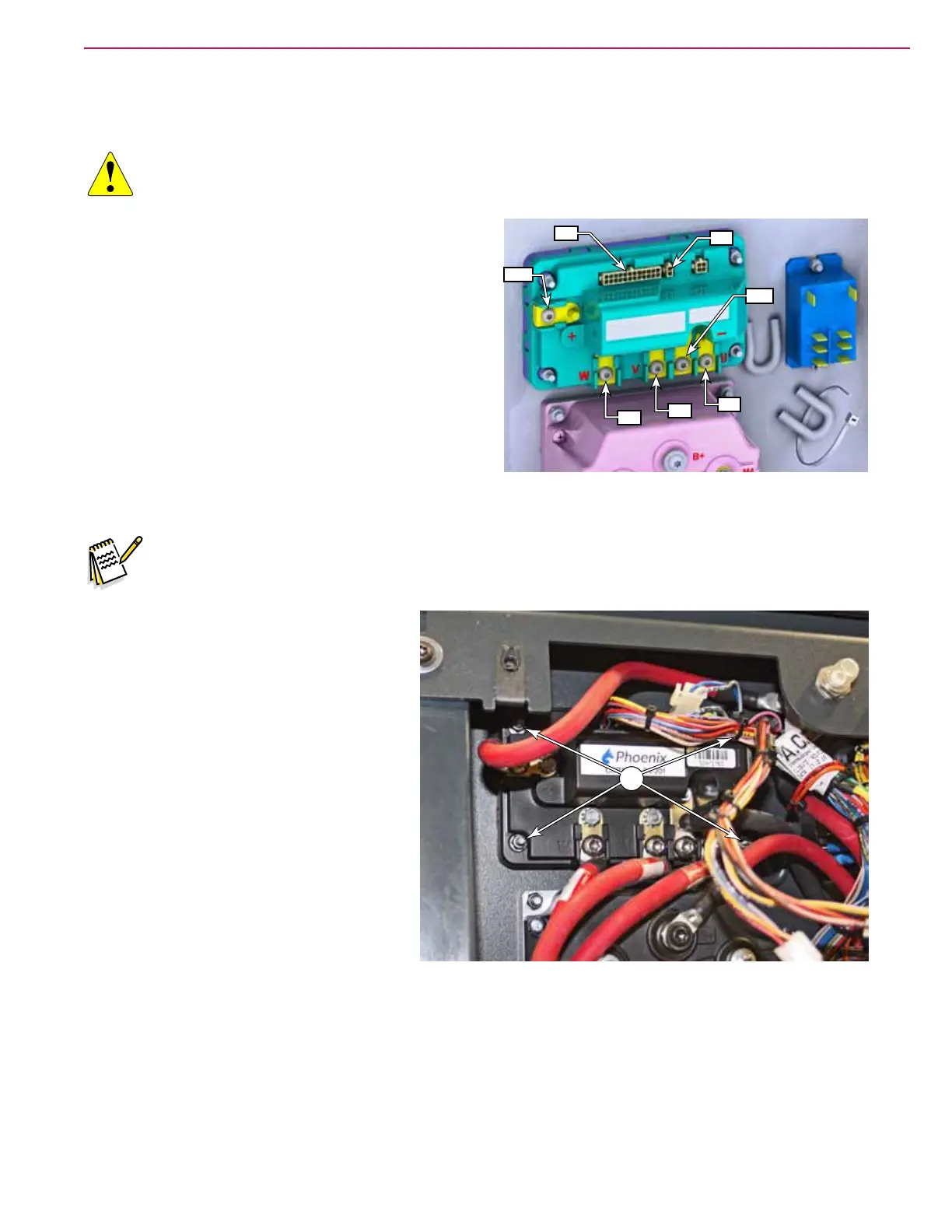
7. Remove the 4 nuts (A) from the outer
corners of the module that secure the
module to the machine frame, and
remove the module.
Replacement Notes
• When replacing the controller, torque the
nuts to 18 to 19 lb•in (2.1 to 2.2 N•m).
• When replacing the wire lugs, torque the
screws to 28 to 33 lb•in (3.2 to 3.8 N•m).
• After replacement, test the machine drive
functions in an open area to ensure proper
operation.
J4
Bat-
J5
Bat+
U
W
V
A

 Loading...