21Service Manual – SC5000 04 - Control System
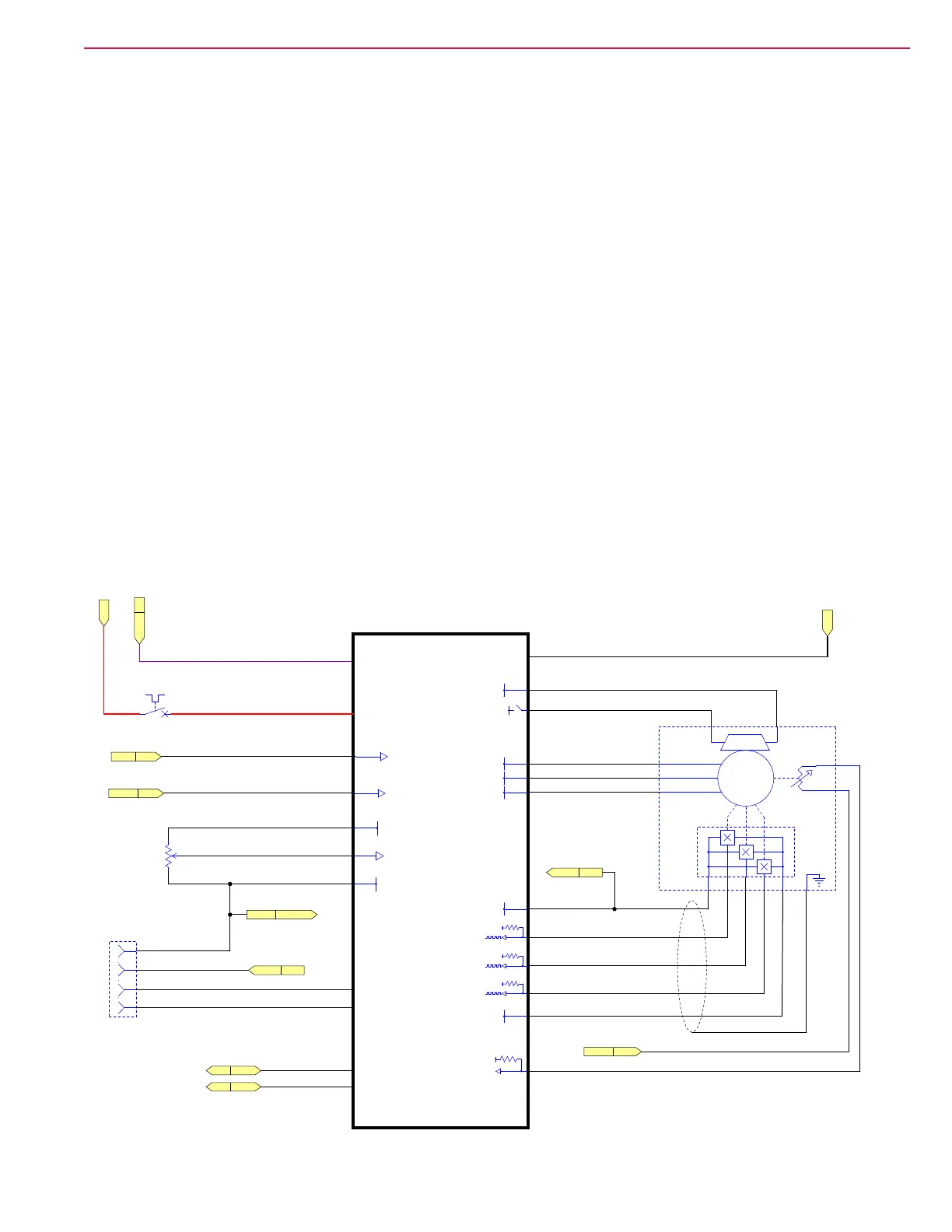
Drive Controller
The drive controller operates and monitors the wheel motor. It generates a 3-phase Pulse Width Modulated
(PWM) power control to the wheel motor. Even though it is actually DC power, it resembles a 3-phase
system because the polarity reversals and zero-crossings resemble a 3-phase AC system. This pseudo
3-phase power permits the wheel motor to achieve full torque at near zero rpm, and very precise position
control.
In order to generate this pseudo 3-phase signal, the drive controller needs to know the exact rotational
position of the rotor inside the wheel motor. This is referred to as Remotely Commutated (i.e. brushless
motor). The motor tells the controller what its rotational position is, and which of its 3 primary windings
should be energized in order to rotate in the desired direction. This is accomplished with a set of 3 hall effect
encoders inside the motor that send pulsed timing signals back to the controller to identify its exact position.
The controller also monitors the internal temperature of the motor to protect it from damage due to
overheating.
The drive controller receives its logic power from the KSI relay, but it also has its own high-power input
through the 70 amp circuit breaker, CB2. When the main machine controller has not energized the KSI
relay, the drive controller is off. The drive controller also has 2 enabling inputs directly from the operator’s
seat switch, and the E-stop button. If either one of these switches is open, the drive is disabled, but has
power.
The drive controller receives forward and reverse direction commands from the Main Machine Controller via
the CANBus, and receives its speed control directly from the operator’s foot pedal. The drive pedal sensor
is a hall effect rotary position sensor with a PWM output that simulates the voltage output from a variable
resistor. The drive controller receives the varying voltage input from 1 to 4 volts. The low voltage 1 is
considered neutral, and as the voltage increases, so does the speed commanded by the operator.
CB2
A4
Drive Controller
Pedal
Drive
EM Brake
Motor
Wheel
[BLDC]
Programmer
Connector
X219
RED/VIO
VIO
BLU
GRY
VIO/YEL
GRY
RED/VIO
PNK/BLU
PNK/YEL
YEL
BLU/GRY
BLU/YEL
VIO
RED
RED
RED
RED
RED
VIO/ORN
GRY
VIO/GRN
RED
BLK
J5-15
J5-9
J5-8
J5-12
J5-21
J5-20
J5-19
J5-18
J5-3
J5-2
J5-22
J5-4
J5-6
J5-13
J5-10
J5-1
B+ Lug
J4-1
J4-2
B- Lug
+5V
B-
15V
15V
15V
M
3Ø
U
Vcc Gnd
H
U
H
V
H
W
V
W
1 2 3 6
3
4
Encoder
4 5
Thermistor
M10
Y1
12
1 2
C
B
A
1
2
3
4
70 AMP
KSI
DATA
CL
EM BRAKE
U1
B-
E-Stop
TEMP SENSOR1
W
I/O GND
V1
WIPER
R4
W1
15V
5V
U
36V
Seat SW
V
CAN(1) L
CAN(1) H
B-
B+
KSI MMC
CAN1HMMC
CAN1LMMC
Batt+
E-Stop MMC
Seat SW MMC
Sig Gnd Thermistor
Sig Gnd DRIVE
15V Out DRIVE
15V Out PROG
Batt-

 Loading...