123Service Manual – SC5000 24 - Electrical System
Device Labeling
Device Numbers (Names):
Each device is given its own unique identier. The letter prex identies the type of device, such as “K” for
a relay, “L” for a solenoid, “M” for motor, and “A” for a control module; just to name a few. Then each device
within that class is given a unique number. For example, “K1” is the main KSI relay. However, because this
particular relay serves a common function, it is also identied by a simple name too: “KSI” (Legacy for Key
Switch Input).
Device numbers and device names (when they exist) are synonymous, but device names are preferred
because they are easier to remember, so long as they are unique and descriptive. Device numbers are
frequently used for the machine’s display, where character count is important.
Connector Contact Numbers:
All of the circuit lines going to any of the control modules will have
indicators for their wire color and the connector pin-out location.
When 2 colors are listed for a wire color, the rst color is the main
color and the second color is the color of a stripe on the wire.
For the connector identier example shown (J4-6), the rst part “J4”
represents the connector number, and the last part “6” represents the pin number within that connector.
This information, along with the “Electrical Connector Pin-Out Assignments” on page 153 is used locate the
physical wires on the machine.
Navigation
In some cases it is necessary to have references across different areas of a drawing. These references
can point across the drawing sheet, or to different sheets in a multi-sheet schematic. The references are
commonly referred to as “Tags”. At a minimum, tags typically have a name or designation, but they may also
contain coordinate pointers to their counterpart.
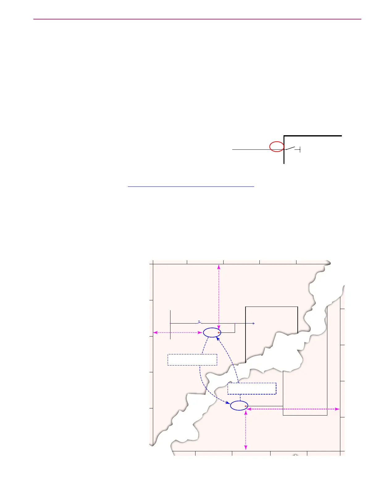
In the sample diagram to the right,
the output from the seat switch needs
to connect to the main controller on
sheet #1 and also to the drive controller
on sheet #3. The identifying name
could be an actual name, such as (Seat
Switch), or in this case, just a letter
designator (G). Both ends of a tag will
have the same identier.
In addition to the identier, the tag
also contains coordinate information to
help you locate the mating tag faster.
So the rst tag contains the coordinates
of the second tag, and the second tag
contains the coordinates of the rst tag.
The format of these coordinates are
Sheet, Column, and Row.
These coordinates are part of the
default title blocks on engineering
drawings, and run around the
perimeter of the drawing sheet. The
columns are represented by the letters
across the top/bottom of the drawing,
and the rows are represented by
the numbers down the sides of the
drawing.
J4-6
Function
Name
ORN/GRN
B-
Controller Name
DC GFE
D EA B C
1
2
3
4
5
SHEET 1
SHEET 3
2
3
4
5
J1-12
GRN/BLU
GRN/BLUBLU/RED
(G) TO 3E4
S1
SW , SEAT
12
E2
MAIN CONTROL BOARD
INTERLOCK
E4
WHEEL-DRIVE
CONTROLLER
J4-9
GRN/BLU
(G) TO 1B2
Point Name = G to
Sheet 3 @ Coordinate E4
Point Name = G to
Sheet 1 @ Coordinate B2

 Loading...