122Service Manual – SC5000 24 - Electrical System
Wiring Diagrams
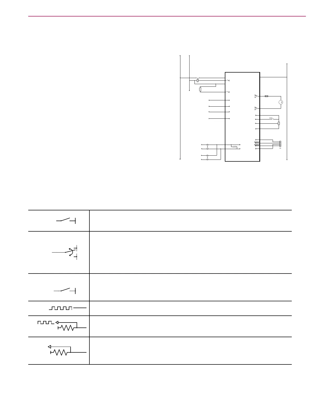
Understanding the Features of the Electrical Circuit Diagram
The electrical circuit diagram is sometimes referred to as a
ladder diagram because it is historically rooted in a type of
schematic that resembled the rungs of a ladder. Over time
it has evolved into a hybrid ladder diagram, specically to
accommodate the presence of intelligent control modules
that drive the system components. (Such as the main
controller and power module, for example.) Even as a hybrid
diagram, it still maintains some of the features of a true
ladder diagram.
Positive voltage source(s) are represented by vertical
“Rails” on the left side of the diagram, and the negative
voltages source (typically only 1, being battery negative)
is represented by a vertical Rail on the right side of the
diagram. Devices are drawn between the two rails, and
current ows from the positive rail, through the load, and to
the negative rail.
Unique to the hybrid ladder diagram are the intelligent
controllers that control if and when devices are connected to either positive or negative power. Even though
not technically accurate, circuit symbols have been drawn inside the controller outlines to represent the
electrical function that takes place inside. These represent the function, but not an actual device. For
example, even though a symbol may look like a switch, it cannot be tested as though it was a real switch.
Some of the common controller internal symbols are described below:
B-
Output, Switch to positive or negative power.
The controller serves to complete the circuit to the respective power source, most
commonly battery negative.
B-
B+
Output, Bi-directional switch to power
These outputs are always in pairs, and are for reversible loads.
• For forward direction, one output is positive and the other is negative.
• For reverse direction, one output is negative and the other is positive.
• For no movement, both outputs are the same, which may be positive, negative, or
zero, depending on the controller.
PWM
B-
Pulse Width Modulation (PWM) Switch
This is an electronic (transistor) switch that completes the circuit to either battery
positive or battery negative power. The duty cycle between on and off states
determines how much power the load receives.
SCLK
Digital Data Out
This symbol indicates that the output is a digital stream of data pulses.
+3.3V
Digital Data In, with Pullup
This symbol represents a digital data stream input signal that is active-low, and the
pullup resistor represents the open-circuit (inactive) signal voltage.
+5V
Discrete Input with Pullup
This symbol represents a binary (On/Off) input with a 5-volt pullup resistor. When the
switch or sensor is off (open circuit) the pullup resistor makes the input equal 5 volts.
When the switch or sensor is closed, the input typically goes to 0 volts.
B-
J4-10
B+
J4-19
CURTIS 1229
DRIVE WHEEL CONTROLLER
J4-14
J4-1
J4-2
J4-17
J4-16
J4-4
J4-3
J4-20
KSI
J4-13
J4-11
J4-18
J4-6
J4-9
J4-12
M1
M2
M1
ORN
BLU/VIO
RED/GRN
YEL/BLK
YEL/WHT
GRN/ORN
VIO/BLK
BLK/WHT
BLU/BLK
GRN/GRY
BLK
YEL
GRN
POT 1
POT 2
J4-8
(V) TO 2A1
(W) TO 4A3
(B) TO 2A1
(C) TO 4A4
(AA) TO 1B2
(AB) TO 1B2
(AC) TO 4B3
(AD) TO 5B4
(AF) TO 2E1
(AG) TO 4E4
ANALOG GND
DRIVER 1
DRIVER 2
SWITCH 1
SWITCH 2
SWITCH 3
SWITCH 4
A3
BLU/RED
REDRED
YEL/BLU
BLK
GRN/BLU
GRY
ORN/GRN
GRY
GRY
GRN
YEL
B+
STEERING READY
AUTO OK
KSI
B-
OPERATOR PRESENCE SW
E-STOP MAIN CONTROL BOARD
CAN1 L, (R) TO 2D2
CAN1 H, (Q) TO 2D3
CAN1 L, (T) TO 4A2
CAN1 H, (S) TO 4A2
B+
KSI
B-
B-
B-
+5V
F6
FUSE, 40 A.
1 2
K3
3 4
1 2
B-
B-
B+
+17V
SW14
X1
1
2
3
4
B-
B+
B-
Y1
EM BRAKE
1 2
R1
C
B
A
M
-
+

 Loading...