172Service Manual – SC5000 30 - Solution System
Solution Level Indication is not Correct
The solution level sensor is comprised of 3 independent sensor bodies working together. This is important to
understand for the purposes of troubleshooting, because one sensor can fail and not affect the other 2. This
could give unexpected results on a machine, such as displaying less uid than what is actually in the tank,
but no error is detected.
For example, if the bottom sensor were to fail, the MMC would
report that the tank was empty until the 2nd sensor detected
uid, and even then, it would report that the tank was only
1/3 full. Then when the 3rd sensor was active, the MMC would
report that the tank was only 2/3 full, when it is actually full.
Testing individual sensor bodies
Because the capacitive sensing technology is also used for
touch-sense circuits, the easiest method for manually activating
a sensor body is to use the capacitive nature of your own hand.
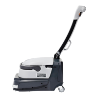
The crosshair on the back of the sensor body represents the
location of the sensing element, and if you simply place your
ngers over the crosshair, you can see the display value on the
Service menu change to indicate that the sensor is active.
In the event that you cannot safely put your hand over the
sensor, you can also use a piece of conductive metal, such as a
stainless steel ruler, a piece of wire, a screwdriver, or even a piece of tin foil; as long as you hold one end of
the metal in your hand.
When you activate or deactivate a sensor body, keep in mind that
the Controller intentionally slows down the change in voltage across
the sensing resistor to avoid sloshing water from causing misleading
results. So it may take several seconds for the value to completely
change from one state to another.
Symptom: The controller indicates the tank is not full when the
tank is actually full. (The Service Menu displays less than 0.55V or
5.5 mA)
• One or more of the sensor bodies is not functioning, so the entire assembly must be replaced. Because
the replacement procedure requires the recovery tank to be removed, drain both the recovery and
solution tanks, remove the recovery tank, and conrm the diagnosis by testing each sensor manually
• If all 3 sensor bodies appear to be functioning with manual activation, the most likely cause is corrosion
in the electrical connector(s) causing a reduction in current ow.
Symptom: The controller reports the tank is empty when it is full. (The Service Menu displays zero volts/
amps).
1. Disconnect the J2 connector from the Controller, and check for a short between J2-3 and Chassis ground
(not J2-9).
• A short between J2-3 and J2-9 is not suspected, because the controller would be reporting amperage
ow and/or an error.
• If a short is detected, repair/replace the harness between the Controller and X190.
• Otherwise, continue.
2. Reconnect J2 and power the machine. Check the voltage between J2-3 and J2-9 for 5 volts.
• If 5 volts is not present, replace the controller.
• Note that a short circuit was already eliminated as a possible cause.
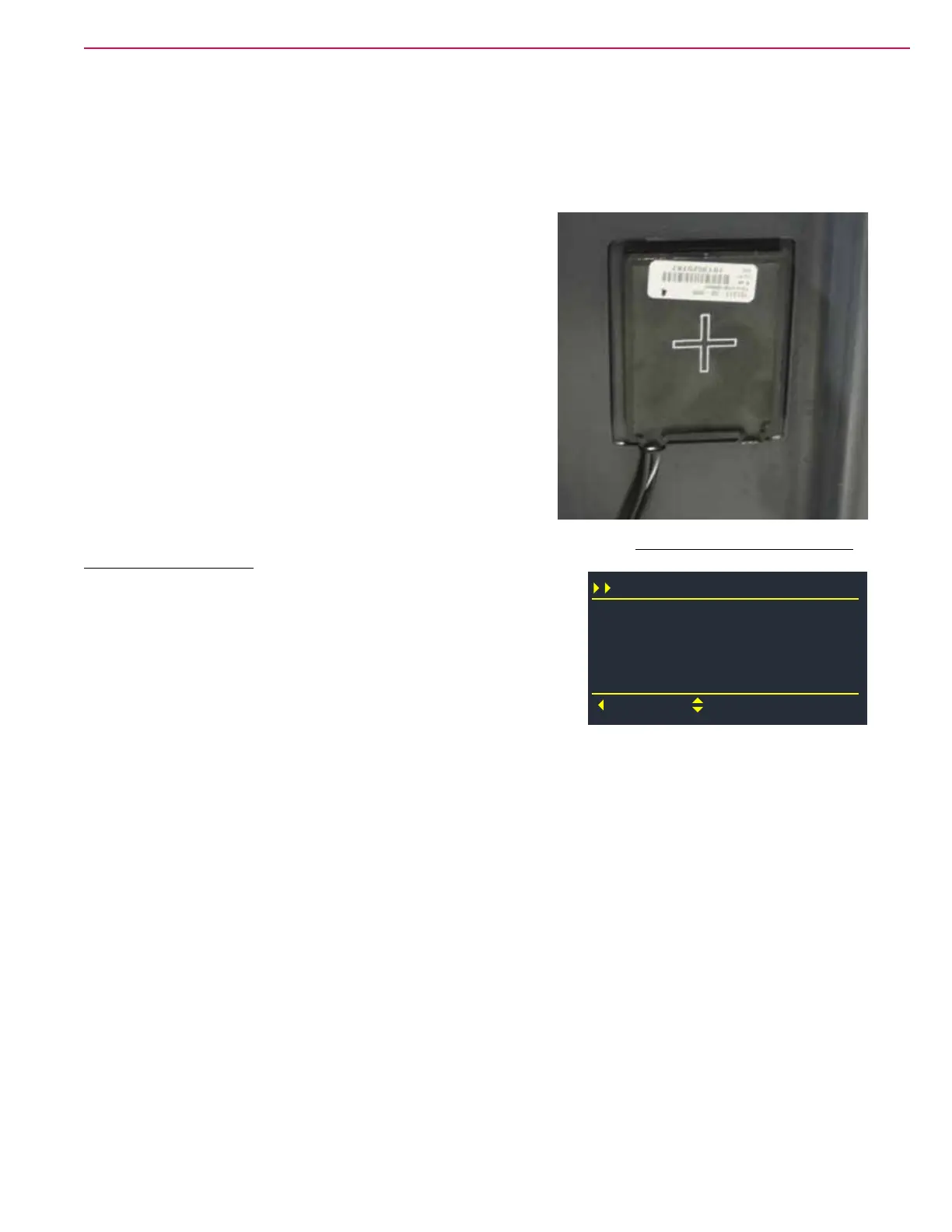
A1 Main Controller
J2-3 SOLUTION LEVEL
Back
Scroll
J1-14 SOLUTION SOL
M24 DETERGENT PUMP
0.44
Off
Off

 Loading...