11.17 E1-03 [V/f Pattern Selection] Dependent Parameters
486 SIEPYEUOQ2A01A AC Drive Q2A Technical Manual
11.17 E1-03 [V/f Pattern Selection] Dependent Parameters
The values for the parameters in these tables depend on the values for parameter A1-02 [Control Method] and E1-
03 [V/f Pattern Selection]. Changing the settings for A1-02 [Control Method] and E1-03 [V/f Pattern Selection]
will change the default settings.
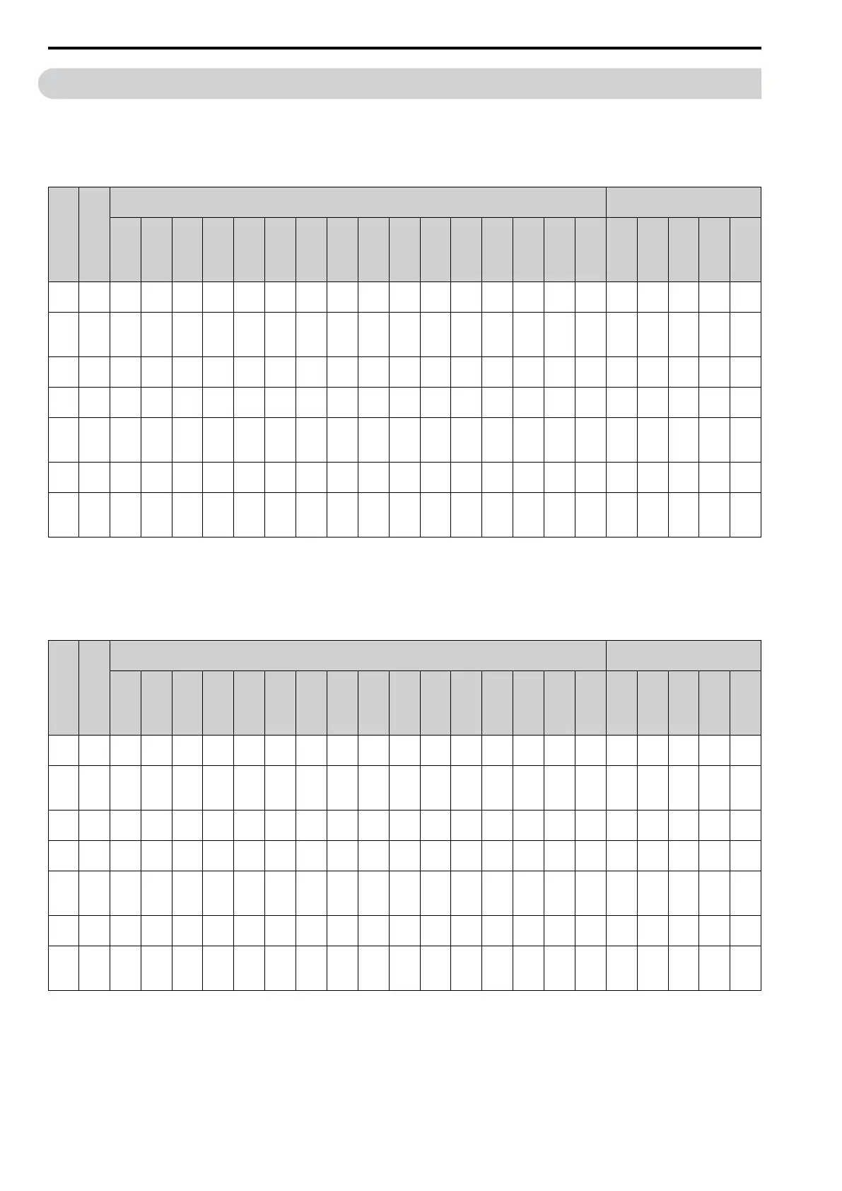
Table 11.1 Parameters Changed by E1-03 (4002 to 4012)
No. Unit
Setting of E1-03 [V/f Pattern Selection]
Setting of A1-02 [Control
Method]
0 1 2 3 4 5 6 7 8 9 A B C D E
F
*1
OL
Vec
tor
(2)
CLVe
ctor
(3)
PM
OL
Vec
tor
(5)
PM
AOL
Vec
tor
(6)
PM
CLVe
ctor
(7)
E1-
04
Hz 50.0 60.0 60.0 72.0 50.0 50.0 60.0 60.0 50.0 50.0 60.0 60.0 90.0 120.0 180.0 50.0 50.0 50.0
*2 *2 *2
E1-
05
*3
V 200.0 200.0 200.0 200.0 200.0 200.0 200.0 200.0 200.0 200.0 200.0 200.0 200.0 200.0 200.0 200.0 200.0 200.0
*2 *2 *2
E1-
06
Hz 50.0 60.0 50.0 60.0 50.0 50.0 60.0 60.0 50.0 50.0 60.0 60.0 60.0 60.0 60.0 50.0 50.0 50.0
*2 *2 *2
E1-
07
Hz 2.5 3.0 3.0 3.0 25.0 25.0 30.0 30.0 2.5 2.5 3.0 3.0 3.0 3.0 3.0 2.5 3.0 0.0 - - -
E1-
08
*3
V 15.0 15.0 15.0 15.0 35.0 50.0 35.0 50.0 19.0 24.0 19.0 24.0 15.0 15.0 15.0 15.0 14.4 0.0 - - -
E1-
09
Hz 1.3 1.5 1.5 1.5 1.3 1.3 1.5 1.5 1.3 1.3 1.5 1.5 1.5 1.5 1.5 1.3 0.5 0.0
*2 *2
0.0
E1-
10
*3
V 9.0 9.0 9.0 9.0 8.0 9.0 8.0 9.0 11.0 13.0 11.0 15.0 9.0 9.0 9.0 9.0 3.0 0.0 - - -
*1 These values are the default settings for E1-04 [Max Output Frequency] through E1-10 [Min Output Voltage] and E3-04 [M2 Max
Out Frequency] through E3-10 [M2 Min Out Voltage]. These settings are the same as those for the V/f pattern when E1-03 = 1 [V/f
Pattern Selection = CT_60-60Hzmax].
*2 The default setting varies depending on the setting of E5-01 [PM Mot Code Selection].
*3 This is the value for 200 V class drives. Double the value for 400 V class drives.
Table 11.2 Parameters Changed by E1-03 (4018 to 4103)
No. Unit
Setting of E1-03 [V/f Pattern Selection]
Setting of A1-02 [Control
Method]
0 1 2 3 4 5 6 7 8 9 A B C D E
F
*1
OL
Vec
tor
(2)
CLVe
ctor
(3)
PM
OL
Vec
tor
(5)
PM
AOL
Vec
tor
(6)
PM
CLVe
ctor
(7)
E1-
04
Hz 50.0 60.0 60.0 72.0 50.0 50.0 60.0 60.0 50.0 50.0 60.0 60.0 90.0 120.0 180.0 50.0 50.0 50.0
*2 *2 *2
E1-
05
*3
V 200.0 200.0 200.0 200.0 200.0 200.0 200.0 200.0 200.0 200.0 200.0 200.0 200.0 200.0 200.0 200.0 200.0 200.0
*2 *2 *2
E1-
06
Hz 50.0 60.0 50.0 60.0 50.0 50.0 60.0 60.0 50.0 50.0 60.0 60.0 60.0 60.0 60.0 50.0 50.0 50.0
*2 *2 *2
E1-
07
Hz 2.5 3.0 3.0 3.0 25.0 25.0 30.0 30.0 2.5 2.5 3.0 3.0 3.0 3.0 3.0 2.5 3.0 0.0 - - -
E1-
08
*3
V 14.0 14.0 14.0 14.0 35.0 50.0 35.0 50.0 18.0 23.0 18.0 23.0 14.0 14.0 14.0 14.0 13.2 0.0 - - -
E1-
09
Hz 1.3 1.5 1.5 1.5 1.3 1.3 1.5 1.5 1.3 1.3 1.5 1.5 1.5 1.5 1.5 1.3 0.5 0.0
*2 *2
0.0
E1-
10
*3
V 7.0 7.0 7.0 7.0 6.0 7.0 6.0 7.0 9.0 11.0 9.0 13.0 7.0 7.0 7.0 7.0 2.4 0.0 - - -
*1 These values are the default settings for E1-04 [Max Output Frequency] through E1-10 [Min Output Voltage] and E3-04 [M2 Max
Out Frequency] through E3-10 [M2 Min Out Voltage]. These settings are the same as those for the V/f pattern when E1-03 = 1 [V/f
Pattern Selection = CT_60-60Hzmax].
*2 The default setting varies depending on the setting of E5-01 [PM Mot Code Selection].
*3 This is the value for 200 V class drives. Double the value for 400 V class drives.

 Loading...


