3.3 Main Circuit Wiring
70 SIEPYEUOQ2A01A AC Drive Q2A Technical Manual
3.3 Main Circuit Wiring
This section gives information about the functions, specifications, and procedures necessary to safely and
correctly wire the main circuit in the drive.
NOTICE: Do not solder the ends of wire connections to the drive. Soldered wiring connections can become loose. Incorrect
wiring procedures can cause drive malfunction because of loose terminal connections.
NOTICE: Turn the drive ON (Run) and OFF (Stop) a maximum of one time each 30 minutes with the MC on the power source
side to extend the service life of the relay contacts and electrolytic capacitors in the drive. Run and Stop the motor as much as
possible with the drive. The drive can fail if users frequently turn the drive ON and OFF with the MC on the power source side to
Run and Stop the drive. Incorrect operation can decrease the service life of the relay contacts and electrolytic capacitors.
◆ Motor and Main Circuit Connections
WARNING! Electrical Shock Hazard. Do not connect terminals R/L1, S/L2, T/L3, U/T1, V/T2, W/T3, -, +1, +2, +3, B1, or B2 to
the ground terminal. Failure to obey can cause death, serious injury, or damage to equipment.
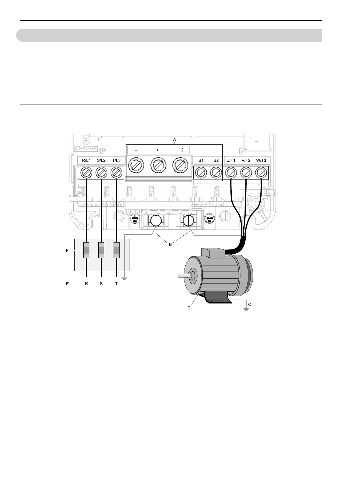
A - DC bus terminal
B - Connect to the drive ground
terminal.
C - Ground the motor case.
D - Three-Phase Motor
E - Use R, S, T for input power
supply.
F - Input Protection (Fuses or Circuit
Breakers)
Note:
The location of terminals are different for different drive models.
Figure 3.2 Wiring the Main Circuit and Motor

 Loading...


