Parameter Details
12
12.6 F: OPTIONS
SIEPYEUOQ2A01A AC Drive Q2A Technical Manual 637
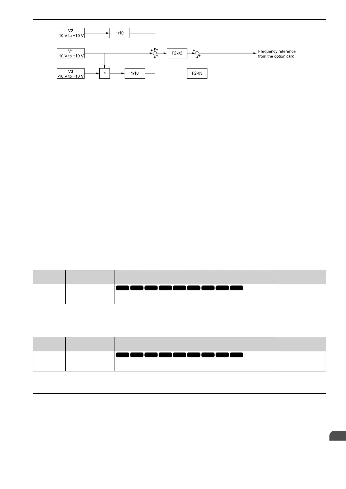
Figure 12.71 Analog Input Reference Addition Input Block Diagram
Use F2-02 and F2-03 to Adjust the Input Status
When the bias set in F2-03 is 0%, the gain in F2-02 and the addition input value set the ratio (%) of the maximum
output frequency output as the frequency reference.
Note:
A voltage input of 10 Vor a current input of 20 mA is the 100% value for each channel.
The bias set in F2-03 sets the ratio (%) of the maximum output frequency output as the frequency reference when
the addition input value is 0%.
Note:
A voltage input of 0 Vor a current input of 4 mA is the 0% value for each channel.
• Example 1:
When the gain set in F2-02 is 50%, the bias set in F2-03 is 0%, and the addition input value is 100%, the
frequency reference is 50% of the maximum output frequency. When the addition input value is 200%, the
frequency reference is 100% of the maximum output frequency.
• Example 2:
When the gain set in F2-02 is 200%, the bias set in F2-03 is 0%, and the addition input value is 50%, the
frequency reference is equivalent to the maximum output frequency. The frequency reference will not be more
than the maximum output frequency, although the addition input value is 50% or higher.
• Example 3:
When the gain set in F2-02 is 100%, the bias set in F2-03 is 30%, and the addition input value is 0%, the
frequency reference is 30% of the maximum output frequency. When the addition input value is 70%, the
frequency reference will be equivalent to the maximum output frequency. The frequency reference will not be
more than the maximum output frequency, although the addition input value is 70% or higher.
■ F2-02 An.In Option Gain
No.
(Hex.)
Name Description
Default
(Range)
F2-02
(0368)
RUN
An.In Option Gain
Sets the analog reference gain as a percentage when the maximum output frequency is 100%.
100.0%
(-999.9 - +999.9%)
Note:
Set F2-01 = 1 [An.In Funct.Selection = 3 Channels Added Together] to enable this function.
■ F2-03 An.In Option Bias
No.
(Hex.)
Name Description
Default
(Range)
F2-03
(0369)
RUN
An.In Option Bias
Sets the analog reference bias as a percentage when the maximum output frequency is 100%.
0.0%
(-999.9 - +999.9%)
Note:
Set F2-01 = 1 [An.In Funct.Selection = 3 Channels Added Together] to enable this function.
◆ F3: DIGITAL INPUT
F3 parameters set the type of input signal to use with digital input option card DI-A3.
Use these digital inputs to set the frequency reference when you install the DI-A3 card in a drive. Set b1-01 = 3
[Freq. Ref. Sel. 1 = Option PCB] to use this card as the frequency reference input. The input signal is isolated
input of 24 Vdc and 8 mA.
• Binary, 16-bit/BCD, 4-digit input
• Binary, 12-bit/BCD, 3-digit input

 Loading...


