Parameter Details
12
12.7 H: TERMINALS
SIEPYEUOQ2A01A AC Drive Q2A Technical Manual 711
■ 6A: DataLog Error
Setting Function Description
6A DataLog Error
The terminal activates when the drive detects a LoG [Com Error / Abnormal SD card].
■ 90 to 93: Q2pack DO1 to 4
Setting Function Description
90 to 93 Q2pack DO1 to 4
Sets the Q2pack digital output. Refer to the Q2pack online manual for more information.
■ A0 to A7: Q2pack ExDO1 to 8
Setting Value Function Description
A0 to A7 Q2pack ExDO1 to 8
Sets the digital output for the Q2pack DO-A3 option card. Refer to the Q2pack online manual for more information.
■ 100 to 1A7: Inverse Output of 0 to A7
Setting Function Description
100 to 1A7 Inverse Output of 0 to A7
Causes inverse output of the function for the selected MFDO. Uses the last two digits of 1xx to select which function to
inversely output.
For example, set H2-xx = 103 for the inverse output of 3 [Fault].
◆ H3: ANALOG INPUTS
■ Multi-Function Analog Inputs
WARNING! Sudden Movement Hazard. Do test runs and examine the drive to make sure that command references are
configured correctly. If you set the command reference incorrectly, it can cause death, serious injury, or equipment damage from
unwanted motor rotation.
Drives have three analog input terminals, terminals AI1, AI2, and AI3. H3 parameters select the functions set to
these analog input terminals and adjust signal levels.
Table 12.49 shows the functions that you can set to analog input terminals. Use H3-02 [AI1 Function Selection],
H3-06 [AI3 Function Selection], and H3-10 [AI2 Function Selection] to set functions.
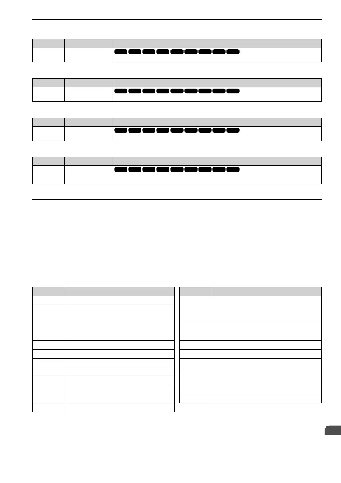
Table 12.49 AI Setting Values
Setting Function
0 Through Mode
1 AuxFreqRef1
2 AuxFreqRef2
3 Freq Ref/BIAS
4 FrqBIAS Frq
5 Freq Gain
6 OutVolt Bias
7 TorqCompensation
8 TorqRef/Lim
9 FW Trq Lim
B Rev Trq Lim
C RegenTrqLim
D GenerTrqLim
Setting Function
E OvUntrq Level
F PID Fbk
10 PID SetPoint
11 Diff PIDFbk
12 AcDcTimeGain
13 DCInjBrakCurr
14 StallPLev@Rn
15 OutFLowLimSel
16 Mot PTC Input
30 Q2pack AI1
31 Q2pack AI2
32 Q2pack AI3
Note:
All analog input scaling uses gain and bias for adjustment. Set the gain and bias values correctly.

 Loading...


