3.3 Main Circuit Wiring
74 SIEPYEUOQ2A01A AC Drive Q2A Technical Manual
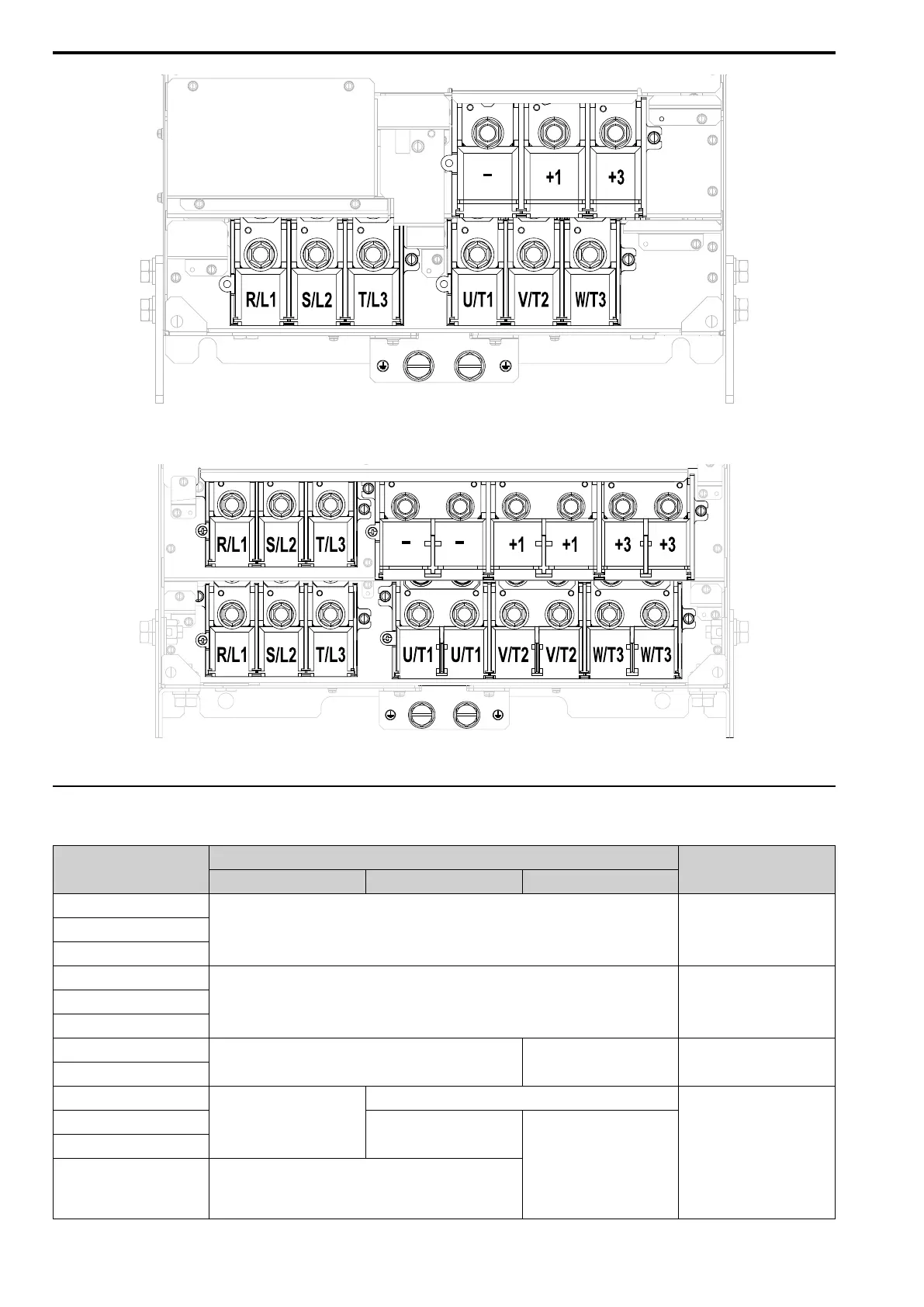
Figure 3.12 Configuration of Main Circuit Terminal Block for Drive Models 4371, 4389
Figure 3.13 Configuration of Main Circuit Terminal Block for Drive Models 4453 - 4675
◆ Main Circuit Terminal Functions
Table 3.1 Main Circuit Terminal Functions
Terminals
Model
Function
4002 - 4044 4060 - 4168 4208 - 4675
R/L1
Main circuit power supply input
To connect a commercial power
supply.
S/L2
T/L3
U/T1
Drive output To connect a motor.V/T2
W/T3
B1
Braking resistor connection -
To connect a braking resistor or
braking resistor unit.
B2
+2
• DC power supply input (+1
and -)
• DC reactor connection (+1 and
+2)
-
To connect peripheral devices, for
example:
• DC power input
• Braking Unit
• DC Reactor
Note:
Remove the jumper between
terminals +1 and +2 to
connect a DC reactor.
+1
DC power supply input (+1 and -)
• DC power supply input (+1
and -)
• Braking unit connection (+3
and -)
-
+3 -

 Loading...


