Electrical Installation
3
3.5 Control Circuit Wiring
SIEPYEUOQ2A01A AC Drive Q2A Technical Manual 89
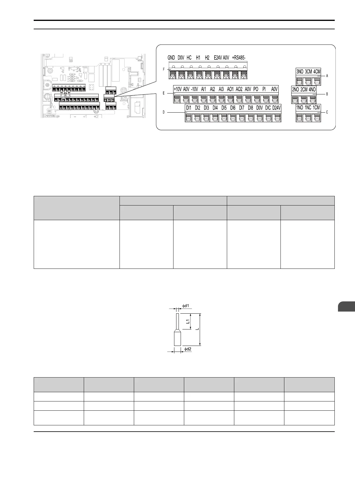
◆ Control Circuit Terminal Configuration
A - Terminal block (TB2-3)
B - Terminal block (TB2-2)
C - Terminal block (TB2-1)
D - Terminal block (TB1)
E - Terminal block (TB3)
F - Terminal block (TB4)
Figure 3.34 Control Circuit Terminal Arrangement
Use the tables in this section to select the correct wires. Use shielded wire for the control circuit terminal block.
Use crimp ferrules on the wire ends to make wiring easier and more reliable.
Table 3.12 Control Circuit Wire Gauges and Tightening Torques
Terminal
Bare Wire Crimp Ferrule
Recommended Gauge
mm
2
(AWG)
Applicable Gauge
mm
2
(AWG)
Recommended Gauge
mm
2
(AWG)
Applicable Gauge
mm
2
(AWG)
DI1 - DI8, D0V, DIC, D24V
H1, H2, HC
PI, +10V, -10V, AI1, AI2, AI3, A0V
PO, AO1, AO2, A0V
RS485+, RS485-, A0V
1NO, 1NC, 1CM, 2NO, 2CM, 3NO, 3CM, 4CO,
4CM
E24V, GND
0.75
(18)
• Stranded wire
0.2 - 1.0
(24 - 18)
• Solid wire
0.2 - 1.5
(24 - 16)
0.5
(20)
0.25 - 0.5
(24 - 20)
■ Crimp Ferrules
Attach an insulated sleeve when you use crimp ferrules.
Use the CRIMPFOX 6, a crimping tool made by PHOENIX CONTACT.
Figure 3.35 External Dimensions of Crimp Ferrules
Table 3.13 Crimp Ferrule Models and Sizes
Wire Gauge
mm
2
(AWG)
Model L (mm) L1 (mm) φd1 (mm) φd2 (mm)
0.25 (24) AI 0.25-8YE 12.5 8 0.8 2.0
0.34 (22) AI 0.34-8TQ 12.5 8 0.8 2.0
0.5 (20)
AI 0.5-8WH,
AI 0.5-8OG
14 8 1.1 2.5
◆ Wiring the Control Circuit Terminal
WARNING! Electrical Shock Hazard. Do not remove covers or touch circuit boards while the drive is energized. Failure to obey
can cause death or serious injury.

 Loading...


