Electrical Installation
3
3.5 Control Circuit Wiring
SIEPYEUOQ2A01A AC Drive Q2A Technical Manual 85
3.5 Control Circuit Wiring
This section gives information about wiring the control circuit.
◆ Control Circuit Connection Diagram
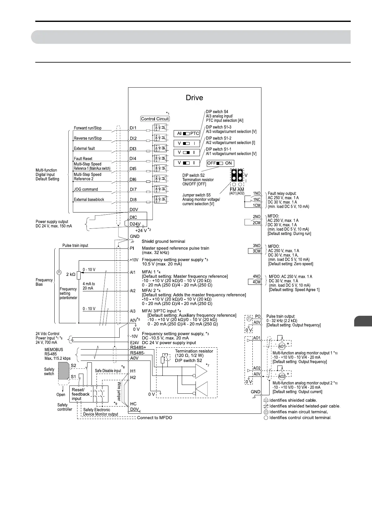
Wire the drive control circuit as shown in Figure 3.33.
Figure 3.33 Control Circuit Connection Diagram
*1 To operate the control circuit while the main circuit power supply is OFF, connect a 24 V power supply unit
(option).
*2 Install a wire jumper between terminals DIC-D24V-D0V to select the type of the power supply for MFDI
(sinking/sourcing mode or internal/external power supply).
NOTICE: Do not close the circuit between terminals D24V and D0V. Failure to obey will cause damage to the drive.
• Sinking Mode: Install a jumper between terminals DIC and D24V.

 Loading...


