32—VGA Main Display CH VIEW Screens
414 www.RolandUS.com Roland VS-2400CD Owner’s Manual
DIR (DIRECT) 1-8 Selector
Channel-Specific Parameter Strips
At the left side of each CH VIEW screen is a strip that contains parameters specific to
the selected type of channel.
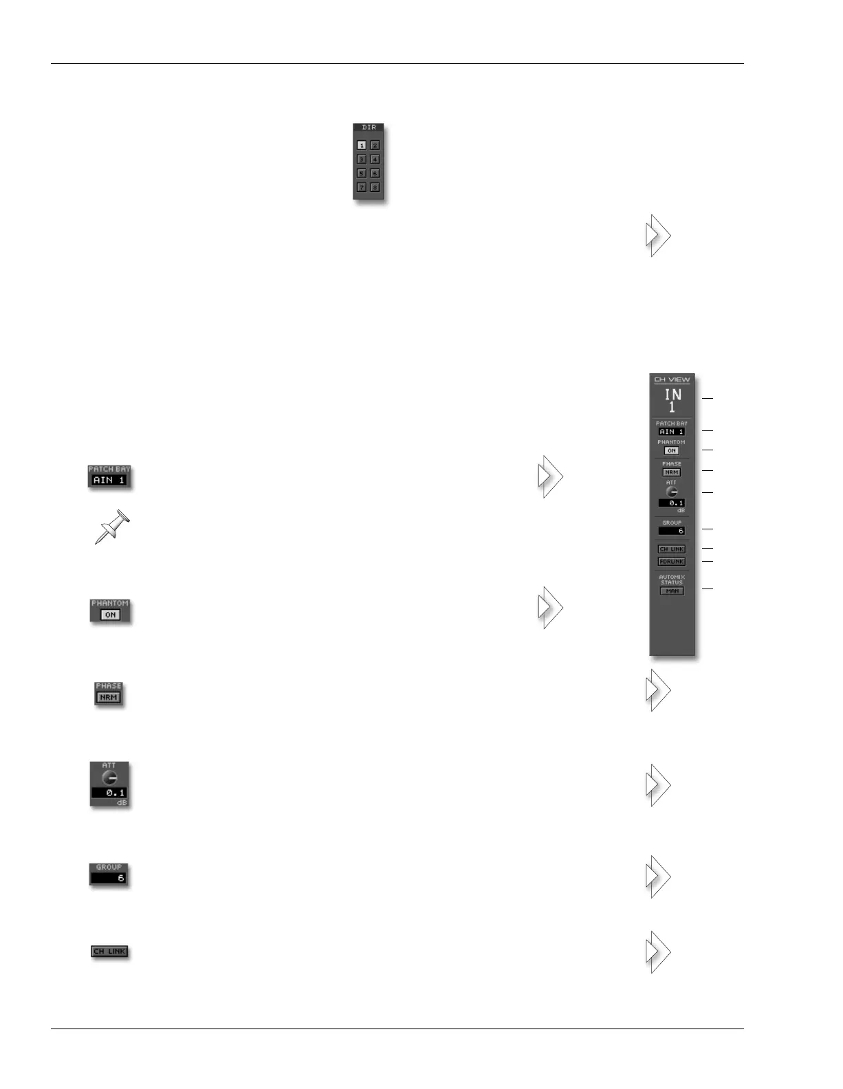
Input Channel Parameter Strip
1. Channel Name
2. PATCH BAY Selector
3. PHANTOM Switch
4. PHASE Button
5. ATT Knob
6. GROUP Selector
7. CH LINK Button
To assign an channel’s signal to one of the eight Direct paths, click
the desired bus’s button in the DIR 1-8 selector.
Click PATCH BAY to reveal a menu from which you
can select the source of the channel’s input signal.
Inputs are always assignable in pairs, with odd-numbered inputs
being assignable to odd-numbered input channels, and so on.
Click PHANTOM—so it’s lit—to turn on the
corresponding XLR input jack’s phantom power.
Click PHASE—so it’s lit—to reverse the phase polarity of the
channel’s signal.
To adjust the level of the input signal coming into the input channel,
drag the ATT knob up or down as desired—the readout beneath the
knob shows the current amount of attenuation.
To assign the input channel to a fader group, click GROUP and
select the desired fader group from the pop-up menu.
To link the channel to its odd/even partner so that any changes
made to one channel affect both, click CH LINK to turn it on.
202
160
126
150
148
150
147
VS2400OMUS.book 414 ページ 2006年2月28日 火曜日 午前11時12分
 Loading...