112
4
Depending on the selection in step 3, set the following
parameters.
When [Box] is selected
When [Pattern] is selected
a) The patterns are the same as standard wipe patterns 1 to 24.
You can also make a pattern selection by pressing
[Mask Ptn Select] in the Main Mask menu to display
the Mask Ptn Select menu (1113.1).
Press the desired pattern (1 to 24) to select it, and set
the [Size] and [Soft] parameters.
5
To invert the mask source, press [Mask Invert],
turning it on.
6
When a pattern is selected as a mask source, set the
pattern modifiers as required.
When selecting [Position] and setting the pattern
position
a) See page 136.
When selecting [Multi] and replicating the pattern
a) See page 138.
When selecting [Aspect] and adjusting the pattern
aspect ratio
a) See page 137.
When selecting [Angle] in the <Rotation> group
and slanting the pattern
a) See page 137.
When selecting [Speed] in the <Rotation> group
and rotating the pattern at a constant speed
a) See page 137.
Using the sub mask
1
Open the M/E-1 >Key1 >Sub Mask menu (1114).
2
In the <Mask Type> group, select the mask type.
Key Mask: Masks a part of a key.
Bkgd Mask: Masks a part of a background.
3
In the <Mask Source> group, select the mask source.
Wipe: Wipe pattern selected for a transition.
Press [Pattern Select] to open the M/E-1 >Wipe
>Main Pattern menu (1151), and select a pattern
and set modifiers (see page 131).
In patterns selected for a mask, modifiers for wipe
direction and edges are disabled.
Utility 1 Bus: Signal selected on the utility 1 bus.
On the cross-point control block, press delegation
button [UTL1] on the cross-point pad and select a
signal using the cross-point buttons in the 1st row/
2nd row.
• On the cross-point control block in key/AUX bus
delegation mode, press the [UTIL1] button in the 1st
row and select a signal using the cross-point buttons
in the 2nd row.
• You can assign the utility 1 bus using the [UTIL]
button on the cross-point pad of the cross-point
control block (see page 73).
• You can assign a utility 1 bus delegation button to
the 1st row or 2nd row of the AUX bus control block
(AUX bus operation mode) in the Setup menu (see
page 382).
4
Depending on the selection in step 3, set the following
parameters.
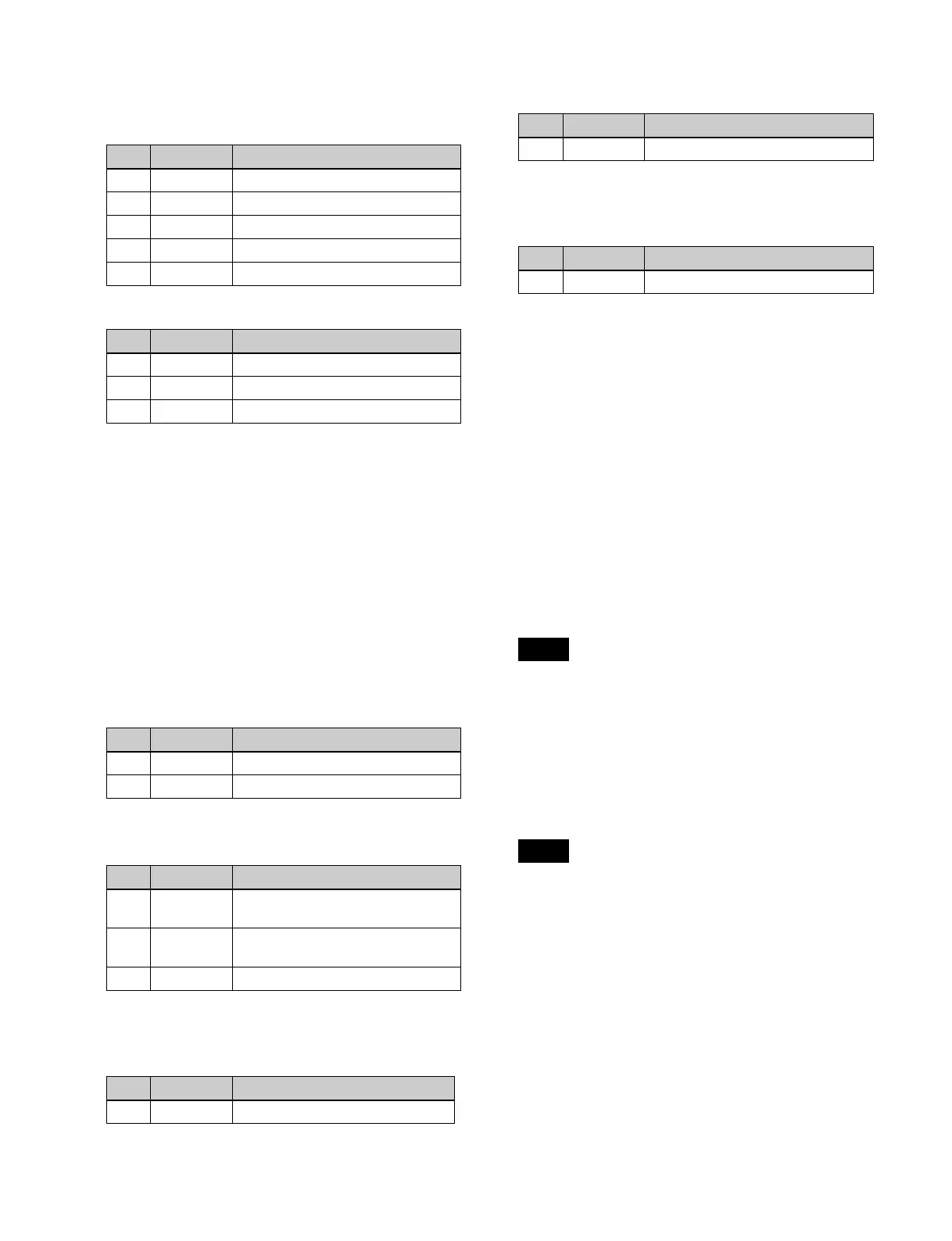
No. Parameter Adjustment
1 Top Position of top side
2 Left Position of left side
3 Right Position of right side
4 Bottom Position of bottom side
5 Soft Degree of softness of box
No. Parameter Adjustment
1 Size Pattern size
2 Soft Degree of softness of pattern edge
5 Pattern Pattern number
a)
No. Parameter Adjustment
1 Position H Horizontal position
a)
2 Position V Vertical position
a)
No. Parameter Adjustment
1 H Multi Number of repetitions of pattern
horizontally
2 V Multi Number of repetitions of pattern
vertically
3 Invert Type Pattern layout
a)
No. Parameter Adjustment
1 Aspect Aspect ratio
a)
No. Parameter Adjustment
1 Angle Rotation angle of pattern
a)
No. Parameter Adjustment
1 Speed Rotation speed of pattern
a)
Note
Notes

 Loading...