378
In the AUX bus control block and other control blocks
which are not included in M/E and P/P rows, the
operations on the utility 2 bus and keys 1 to 8 are not
inhibited (excluding the key fader control block).
1
In the Engineering Setup >Panel >Config menu
(7321), press [Operation Inhibit].
The Operation Inhibit menu (7321.26) appears.
2
Press [M/E Operation Inhibit].
The M/E Operation Inhibit menu (7321.18) appears.
3
Select the target bank to set.
4
In the <M/E Operation Inhibit> group, select the utility
2 bus (Util2 Bus) or key button (Key1 to Key8) for
which operations are to be inhibited.
Inhibiting DME Channel Selection
Operations
You can inhibit DME channel selection operations in the
device control block (trackball).
1
In the Engineering Setup >Panel >Config menu
(7321), press [Operation Inhibit].
The Operation Inhibit menu (7321.26) appears.
2
Press [Trackball Module].
The Trackball Module menu (7321.27) appears.
3
Select the DME channel for which to inhibit operation.
4
Press [Inhibit].
Cross-Point Settings
Creating Cross-Point Assign Tables
You can create a “main” table and up to 14 other tables
(table 1 to table 14) as cross-point assign tables. However,
you can only carry out assignment of video and key
combinations in the main table.
Creating the main table
In the main table, a pair consisting of a video signal and a
key signal is assigned to each button number. You can also
assign the same signal to another button number to
duplicate the assignment. You can also delete currently
assigned signals.
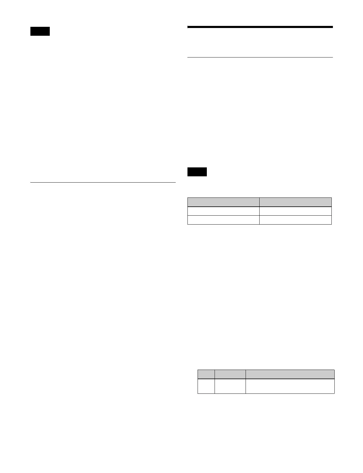
The video/key pair numbers are fixed for the following
button numbers in tables 1 to 14.
The re-entry video/key numbers are set as the pair numbers
by default. Use the defaults as-is, since changing the
settings will make it impossible to select the correct
signals.
1
In the Engineering Setup >Panel >Xpt Assign menu
(7322) or the Engineering Setup >Panel >Xpt Assign
>Table Button Assign menu (7322.1), press [Main, V/
K Pair Assign].
The Main, V/K Pair Assign menu (7322.5) appears.
The left side of the status area shows the video and key
signal names currently assigned in the main table, and
the source numbers. When the shift button is pressed,
the number field is distinguished by color.
The right side of the status area shows a list of source
numbers and assignable signals.
2
Select the target button number to set.
3
In the <Assign> group, select the target signal to set.
Video: Set video signals.
Key: Set key signals.
Note
Note
Button number V/K pair number
281 to 286 211, 221, 231, 241, 251, 261
291 to 296 216, 226, 236, 246, 256, 266
No. Parameter Adjustment
1 V/K Pair No Selection of video and key pair
number
 Loading...