374
3
Press [Link Source Set].
4
Repeat steps 2 and 3 as required to select the matrix
sources to be linked to other cross-point buttons.
To return the set combinations to the defaults
Press [Init Link Table], check the message, then press
[Yes].
Setting the link bus
Make settings for the link number selected in the External
Bus Link menu.
1
In the Engineering Setup >Panel >Config >Link/
Program Button >External Bus Link menu (7321.3),
press [Link Bus Adjust].
The Link Bus Adjust menu (7321.6) appears.
You can also select the link number in this menu using
the [Link No] parameter.
2
Select the switcher bus and the router destination to be
linked to the switcher bus.
3
Perform the following operations.
• To apply the bus, press [Master Bus Set].
• To apply the destination address, press [Linked Dest
Set].
Linking Transitions Between Keyers
1
In the Engineering Setup >Panel >Config menu
(7321), press [Link/Program Button].
The Link/Program Button menu (7321.8) appears.
2
In the <Link> group, press [Key Trans Link].
The Key Trans Link menu (7321.2) appears.
3
Select the keyer to be the master.
4
In the <Key Select> group, select the keyer to link to
the transition of the master.
Linking the next transition selection
buttons
You can add links for the next transition selection buttons
in the transition control block to the transition link settings
between keyers. For example, if two keyers (Key 2 and
Key 3) are linked with the master keyer (Key 1), then
pressing the [KEY1] next transition selection button also
selects the [KEY2] and [KEY3] buttons.
1
Set the transition links between keyers.
For details about the method of operation, see
“Linking Transitions Between Keyers” (page 374).
2
Press [Next Trans Link], turning it on.
The [KEY1] to [KEY8] next transition selection
buttons in the transition control block are coupled
(selected) with the transition links between keyers set
in the Key Trans Link menu.
This setting is common to the Key Trans Link menu
(7321.2). It is not possible to make separate settings
for each master keyer.
Setting the Buttons and Fader
Levers on the Key Fader Control
Block
You can assign keys (KEY1 to KEY8) of any switcher
bank (M/E-1 to M/E-5, PGM/PST) to the key delegation
buttons on the key fader control block.
You can also set the key delegation button for operation by
the fader lever and the “play” (range of movement that
does not start operation) at both ends of the fader lever.
Setting key delegation button assignments
1
In the Engineering Setup >Panel >Config menu
(7321), press [Key Fader Assign].
The Key Fader Assign menu (7321.1) appears.
The status area shows the settings of the key
delegation buttons 1 to 4 and the fader levers for each
module in the key fader control block.
2
Select the target key delegation button to assign in the
status area.
3
In the <ME Select> group, select the bank with the key
to assign.
4
In the <Key Assign> group, select the key to assign.
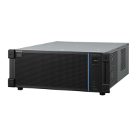
No. Parameter Adjustment
2 Internal
Bus
Switcher bus selection
3 Destination Router destination selection
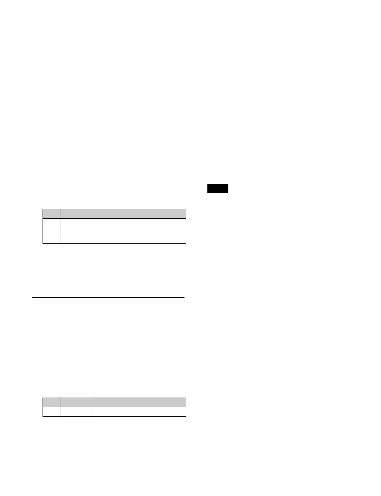
No. Parameter Adjustment
1 Master Key Select keyer to be master
Note
 Loading...