73
Utility bus mode
The following buses can be assigned to the 1st row to 4th
row while the [UTIL] button is pressed on the cross-point
pad of the cross-point control block.
While the [UTIL] button is pressed, the cross-point pad
displays buttons for utility bus mode, and you can switch
the assignment in the 2nd row by pressing the [DME
UTL1] button or [DME UTL2] button.
• 1st row: DME external video bus
• 2nd row: DME utility 1 bus (when [DME UTL1] button
indicator is lit) or DME utility 2 bus (when [DME
UTL2] button indicator is lit)
• 3rd row: Utility 1 bus
• 4th row: Utility 2 bus
You can change the bus assignments of the 1st row to 4th
row in the Setup menu. The following bus assignments are
supported.
- Background A bus, B bus
- Key 1 bus to key 8 bus
The [UTIL] button operation can be set to hold mode or
lock mode.
For details, see “Setting Utility Bus Mode” (page 398)
and “Setting the [UTIL] button operation mode”
(page 394).
• Not available in key/AUX bus delegation mode.
• Not available when dual background bus mode is set.
• If a key bus is assigned using the [UTIL] button, the key
source signal cannot be selected.
Signal Assignment and Selection
Assigning signals to buttons
Each cross-point button has a button number, which you
use to assign a signal.
Signals input to the input connectors (primary inputs 1 to
160) and signals generated within the switcher can be
selected.
Each button has assigned to it a video signal and a key
signal, forming a pair. You can set the video and key
combinations in the Setup menu.
For details, see “Creating Cross-Point Assign Tables”
(page 378).
Cross-point control block button numbers
On the M/E and PGM/PST banks, each cross-point button
has two button numbers, and you use the [SHIFT] button
to switch between these numbers.
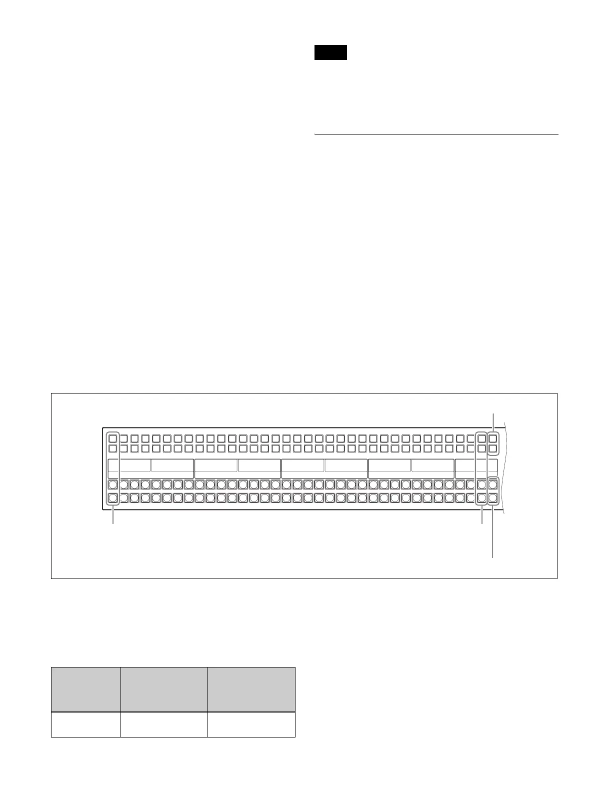
In the case of a 36-button layout, the button numbers are as
follows.
The rightmost (36th) button is used as the [SHIFT] button.
When selecting the signals of button numbers 1 to 35,
press the corresponding cross-point button number. When
selecting the signals of button numbers 36 to 70, press the
[SHIFT] button and the corresponding cross-point button
number.
Notes
SHIFT button
SHIFT button
(first numbers)
(second numbers)
1, 2, 3, 4, …
36, 37, 38, 39, …
…, 33, 34, 35
…, 68, 69, 70
Button Number when the
shift button is not
pressed (unshifted
state)
Number when the
shift button is
pressed (shifted
state)
From left side to
35th
1 to 35 36 to 70
 Loading...