72
a) For buttons that not set by default, assignment is required in the Setup
menu.
b) Dual background bus mode can be selected.
c) Can also be assigned using utility bus mode.
Dual background bus mode
You can select the background A bus (3rd row) shifted
signal in the 1st row, and the background B bus (4th row)
shifted signal in the 2nd row.
To set dual background bus mode, press the [DUAL
BKGD BUS] button on the cross-point pad, turning it on.
• The [DUAL BKGD BUS] button requires an assignment
to have been made in the Setup menu (see page 396).
• For the following state of the switcher banks, dual
background bus mode is not available.
- When set to [Dual M/E Assign]
- When the operation mode (M/E Config) is set to DSK
mode
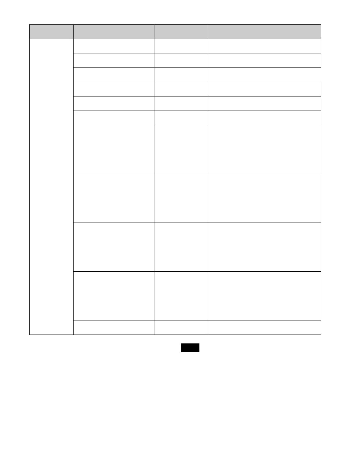
AUX bus control
block (AUX bus
operation mode)
AUX1 bus to AUX48 bus 3rd row, 4th row Press the [AUX 1] to [AUX 48] buttons in the 1st
row/2nd row, turning them on.
Frame memory source 1 bus
Frame memory source 2 bus
3rd row, 4th row Press the [FMS 1] button and [FMS 2] button in
the 1st row/2nd row, turning them on.
Color corrector 1 bus
Color corrector 2 bus
3rd row, 4th row Press the [CCR 1] button and [CCR 2] button in
the 1st row/2nd row, turning them on.
Edit preview bus 3rd row, 4th row Press the [EDIT PVW] buttons in the 1st row/2nd
row, turning them on.
DME1 video bus to DME4 video
bus
3rd row, 4th row Press the [DME1 V] and [DME4 V] buttons in the
1st row/2nd row, turning them on.
DME1 key bus to DME4 key bus 3rd row, 4th row Press the [DME1 K] and [DME4 K] buttons in the
1st row/2nd row, turning them on.
M/E-1 UTILITY 1 and 2 buses
M/E-2 UTILITY 1 and 2 buses
M/E-3 UTILITY 1 and 2 buses
M/E-4 UTILITY 1 and 2 buses
M/E-5 UTILITY 1 and 2 buses
P/P UTILITY 1 and 2 buses
3rd row, 4th row Press the following buttons in the 1st row/2nd
row, turning them on.
[M/E1 UTIL1] button, [M/E1 UTIL2] button
[M/E2 UTIL1] button, [M/E2 UTIL2] button
[M/E3 UTIL1] button, [M/E3 UTIL2] button
[M/E4 UTIL1] button, [M/E4 UTIL2] button
[M/E5 UTIL1] button, [M/E5 UTIL2] button
[P/P UTIL1] button, [P/P UTIL2] button
M/E-1 key 1 to key 8 fill buses
M/E-2 key 1 to key 8 fill buses
M/E-3 key 1 to key 8 fill buses
M/E-4 key 1 to key 8 fill buses
M/E-5 key 1 to key 8 fill buses
P/P key 1 to key 8 fill buses
3rd row, 4th row Press the following buttons in the 1st row/2nd
row, turning them on.
[M/E1 KEY1 V] to [M/E1 KEY8 V] buttons
[M/E2 KEY1 V] to [M/E2 KEY8 V] buttons
[M/E3 KEY1 V] to [M/E3 KEY8 V] buttons
[M/E4 KEY1 V] to [M/E4 KEY8 V] buttons
[M/E5 KEY1 V] to [M/E5 KEY8 V] buttons
[P/P KEY1 V] to [P/P KEY8 V] buttons
M/E-1 key 1 to key 8 source buses
M/E-2 key 1 to key 8 source buses
M/E-3 key 1 to key 8 source buses
M/E-4 key 1 to key 8 source buses
M/E-5 key 1 to key 8 source buses
P/P key 1 to key 8 source buses
3rd row, 4th row Press the following buttons in the 1st row/2nd
row, turning them on.
[M/E1 KEY1 K] to [M/E1 KEY8 K] buttons
[M/E2 KEY1 K] to [M/E2 KEY8 K] buttons
[M/E3 KEY1 K] to [M/E3 KEY8 K] buttons
[M/E4 KEY1 K] to [M/E4 KEY8 K] buttons
[M/E5 KEY1 K] to [M/E5 KEY8 K] buttons
[P/P KEY1 K] to [P/P KEY8 K] buttons
M/E-1 DME external video bus
M/E-2 DME external video bus
M/E-3 DME external video bus
M/E-4 DME external video bus
M/E-5 DME external video bus
P/P DME external video bus
3rd row, 4th row Press the following buttons in the 1st row/2nd
row, turning them on.
[M/E1 DME EXT] button
[M/E2 DME EXT] button
[M/E3 DME EXT] button
[M/E4 DME EXT] button
[M/E5 DME EXT] button
[P/P DME EXT] button
DME utility 1 bus
DME utility 2 bus
3rd row, 4th row Press the [DME UTIL1] and [DME UTIL2]
buttons in the 1st row/2nd row, turning them on.
Control block Bus name Cross-point button
rows
Delegation operation
a)
Notes
 Loading...