12-42 FI SYSTEM DIAGNOSIS
7) Remove the fuel tank. (13-2, -3)
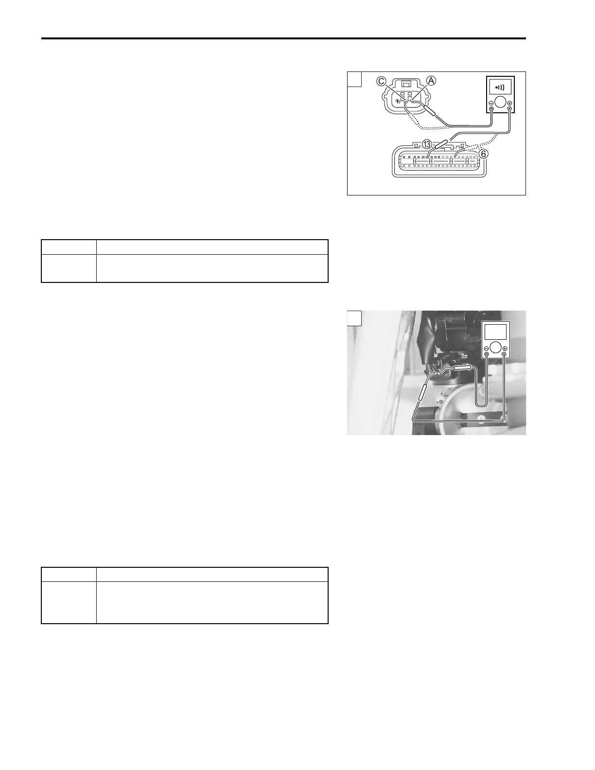
8) Disconnect the ECM coupler. (12-60)
9) Check the continuity between R/Bl wire A and terminal C.
10) Also, check the continuity between G/B wire C and terminal
6.
IAP sensor lead wire continuity: Continuity ()
09900-25008: Multi circuit tester set
09900-25009: Needle-pointed probe set
Tester knob indication: Continuity test ()
Is the continuity OK?
Step 2
1) Remove the seat rail assembly. (19-3)
NOTE:
Do not remove the muffler, when measuring the IAP sensor out-
put voltage.
2) Connect the ECM coupler and IAP sensor coupler.
3) Insert the needle-pointed probes to the lead wire coupler.
4) Kickstart the engine at idle speed.
5) Measure the IAP sensor output voltage at the wire side cou-
pler (between G/B and B/Br wires).
IAP sensor output voltage: 0.23
– 4.10
V at idle speed
(+ G/B – - B/Br)
09900-25008: Multi circuit tester set
09900-25009: Needle-pointed probe set
Tester knob indication: Voltage ()
Is the voltage OK?
YES Go to Step 1. (12-39)
NO
R/Bl wire or G/B wire open, or G/B wire shorted to
ground.
YES Go to Step 3.
NO
• Open or short circuit in the G/B wire.
• If the wire is OK, replace the IAP sensor with a
new one.
1
ECM coupler (Harness side)
V
2

 Loading...


