FI SYSTEM DIAGNOSIS 12-43
Step 3
1) Remove the throttle body. (13-8, -9)
2) Remove the IAP sensor. (12-61)
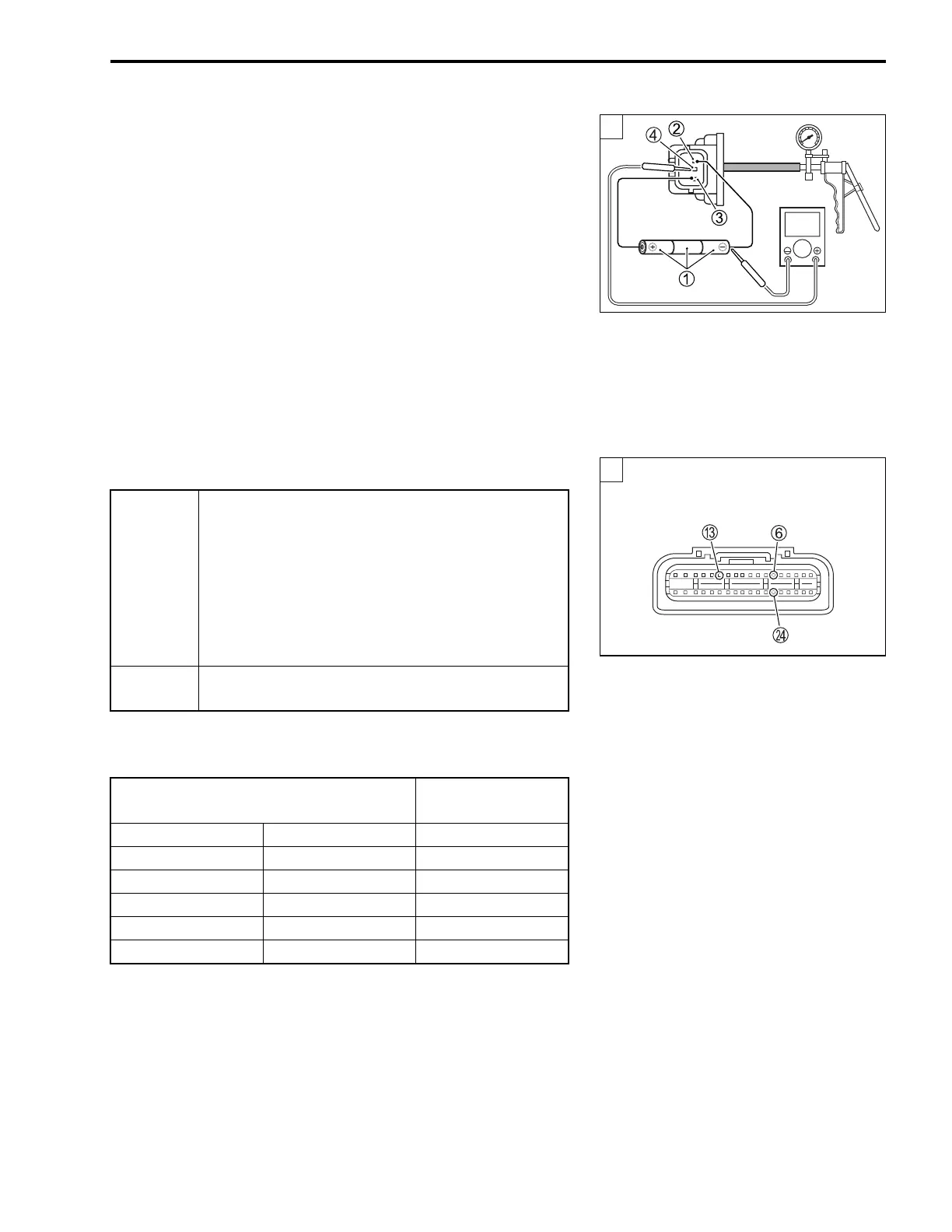
3) Connect the vacuum pump gauge to the vacuum port of the
IAP sensor.
4) Arrange 3 new 1.5 V batteries in series 1 (check that total -
voltage is 4.5 – 5.0 V) and connect - terminal to the ground -
terminal 2 and + terminal to the VCC terminal 3.
5) Check the voltage between Vout 4 and ground. Also, check
if voltage reduces when vacuum is applied by using vacuum
pump gauge.
09917-47011: Vacuum pump gauge
09900-25008: Multi circuit tester set
Tester knob indication: Voltage ()
Is the voltage OK?
Output voltage
(VCC voltage 4.5 – 5.0 V, ambient temp. 25 °C, 77 °F)
YES
• G/B, R/Bl or B/Br wire open or shorted to
ground, or poor 6, C or N connection.
• If wire and connection are OK, intermittent trou-
ble or faulty ECM.
• Recheck each terminal and wire harness for
open circuit and poor connection.
• Replace the ECM with a known good one, and
inspect it again.
NO
If check result is not satisfactory, replace the IAP
sensor with a new one.
ATMOSPHERIC
PRESSURE
OUTPUT
VOLTAGE
(mmHg) kPa (V)
760 100 Approx. 2.86
707 94 Approx. 2.70
634 85 Approx. 2.45
567 76 Approx. 2.21
526 70 Approx. 2.05
3
V
ECM coupler (Harness side)
3

 Loading...


