108 General Information TM9100 Service Manual
© Tait Electronics Limited August 2005
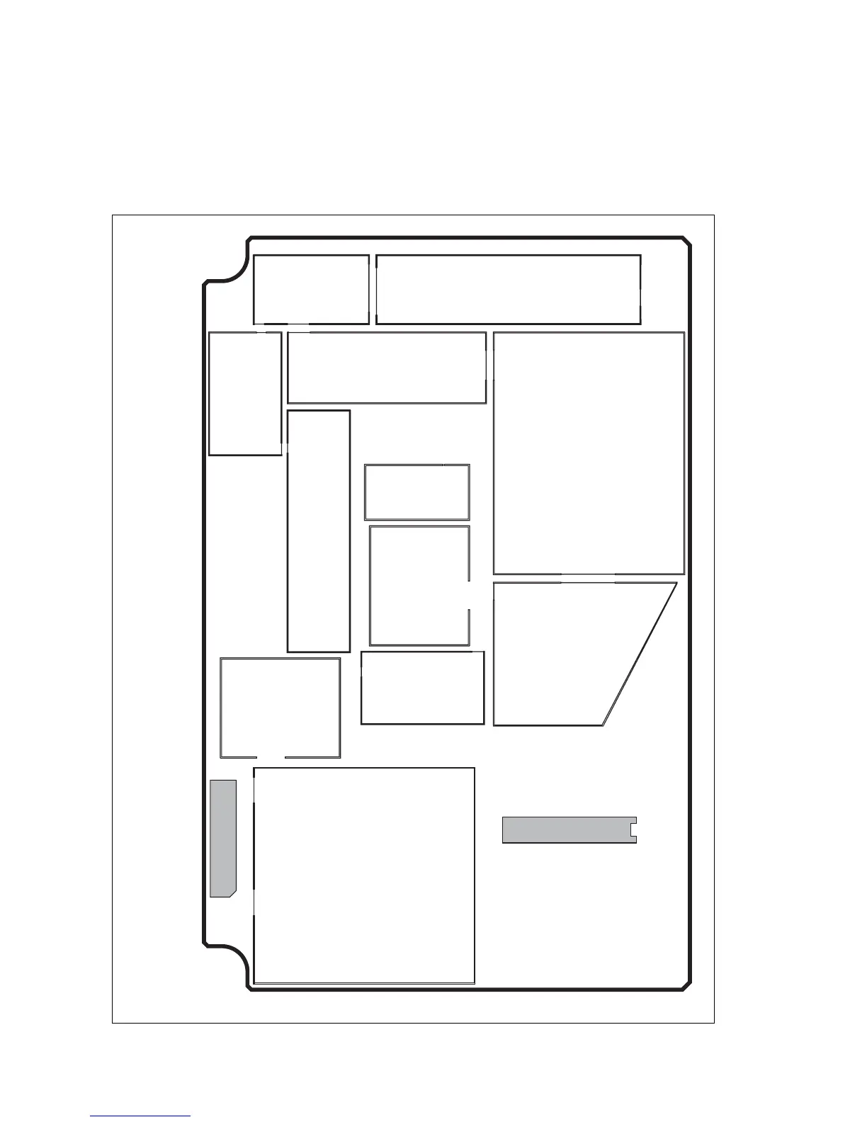
4.6 Shielding Cans and Connectors
The shielding cans on the top- and bottom-side of the main-board
assembly are identified in Figure 4.3 and Figure 4.4. The figures also
show the locations of the connectors on the board.
Figure 4.3 Shielding cans and connectors (top side of main-board assembly)
DIGITAL BOARD
SK102
INTERNAL-OPTIONS
CONNECTOR
PL101
FACTORY
CONNECTOR
PIN TOP LPF TOP
DIRC TOP
FE TOP
VCO TOP
(UHF ONLY)
PAF TOP
IF TOP
SYN TOP
CDC TOP
FCL TOP
PAD TOP
 Loading...


