192 Frequency Synthesizer Fault Finding TM9100 Service Manual
© Tait Electronics Limited August 2005
9.5 Receive VCO and Related Circuitry (UHF Radios)
Introduction If there is no fault with the power supplies, the PLL inputs and output, and
the loop filter, check the VCO and related circuitry. The procedures in this
section apply only to UHF radios with a lock error or receive fault, and
therefore with suspect receive VCO and related circuitry. (The minimum
and maximum receive frequencies for the different UHF frequency bands
are defined in Table 9.2.) There are six aspects:
■ Task 17: check receive VCO
■ Task 18: repair PLL feedback
■ Task 19: repair receive VCO
■ Task 20: check switching to receive mode
■ Task 21: repair switching network
■ Task 22: check receive buffer amplifier
The measurement points for diagnosing faults in the VCO and related
circuitry are summarized in Figure 9.8.
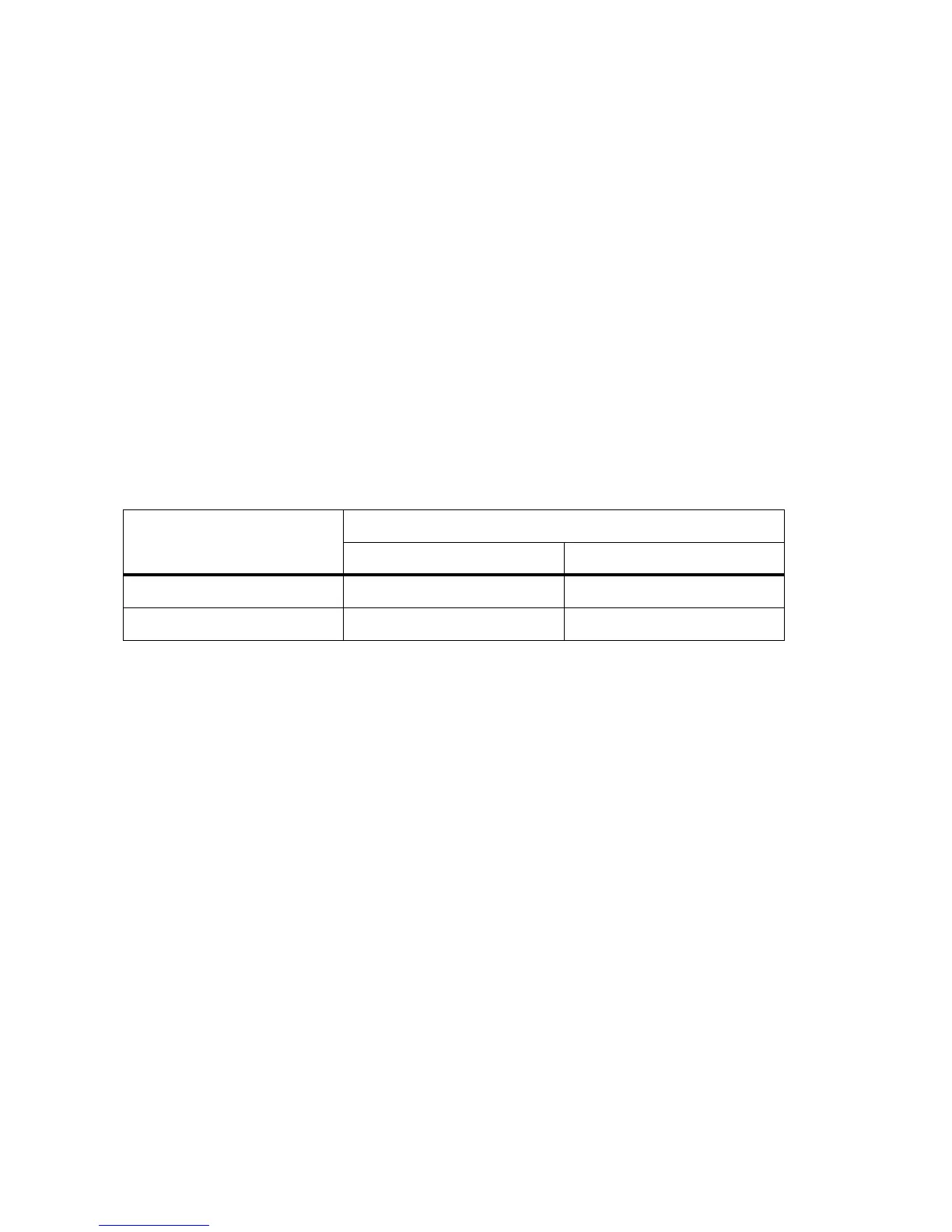
Table 9.2 Minimum and maximum receive frequencies for the different UHF frequency bands
Frequency band Receive frequency in MHz
Minimum Maximum
H5 337 ± 5 441 ± 5
H6 378 ± 5 498 ± 5
 Loading...


