TM9100 Service Manual Receiver Fault Finding 235
© Tait Electronics Limited August 2005
Task 8 —
Moderately Low
Sensitivity
Following the initial investigation in Task 7, check the circuitry as follows
when the sensitivity loss is moderate.
1. Remove the
FE TOP can and, if not already done, the IF TOP can.
2. Check the soldering of all the components of the front-end tuning
circuitry from C400 to T401 (see Figure 10.1 and Figure 10.3).
3. Check the 3V supply voltage at L404; use the measurement point
shown in Figure 10.3.
4. Also check the LNA bias conditions. First measure V
c
between the
collector of Q401 and ground (see Figure 10.3).
5. Secondly, check I
c
. To do so, unsolder and raise one terminal of L404
(tombstone position) (see Figure 10.3), connect a multimeter
between this terminal and the pad for the terminal, and measure the
current.
6. If the checks in Step 2 to Step 5 reveal no fault, go to Step 7. If there
is a fault, repair it and go to Step 8.
7. Check the signal level at the output of LO1 and continue the fault
diagnosis as in “Power Supply for FCL” on page 215.
8. Recalibrate the receiver using the calibration application.
9. Confirm the removal of the fault and go to “Final Tasks” on
page 147. If the repair failed, go to Task 9
.
V
c
: 2.7 ± 0.1V
I
c
: 10 ± 1mA
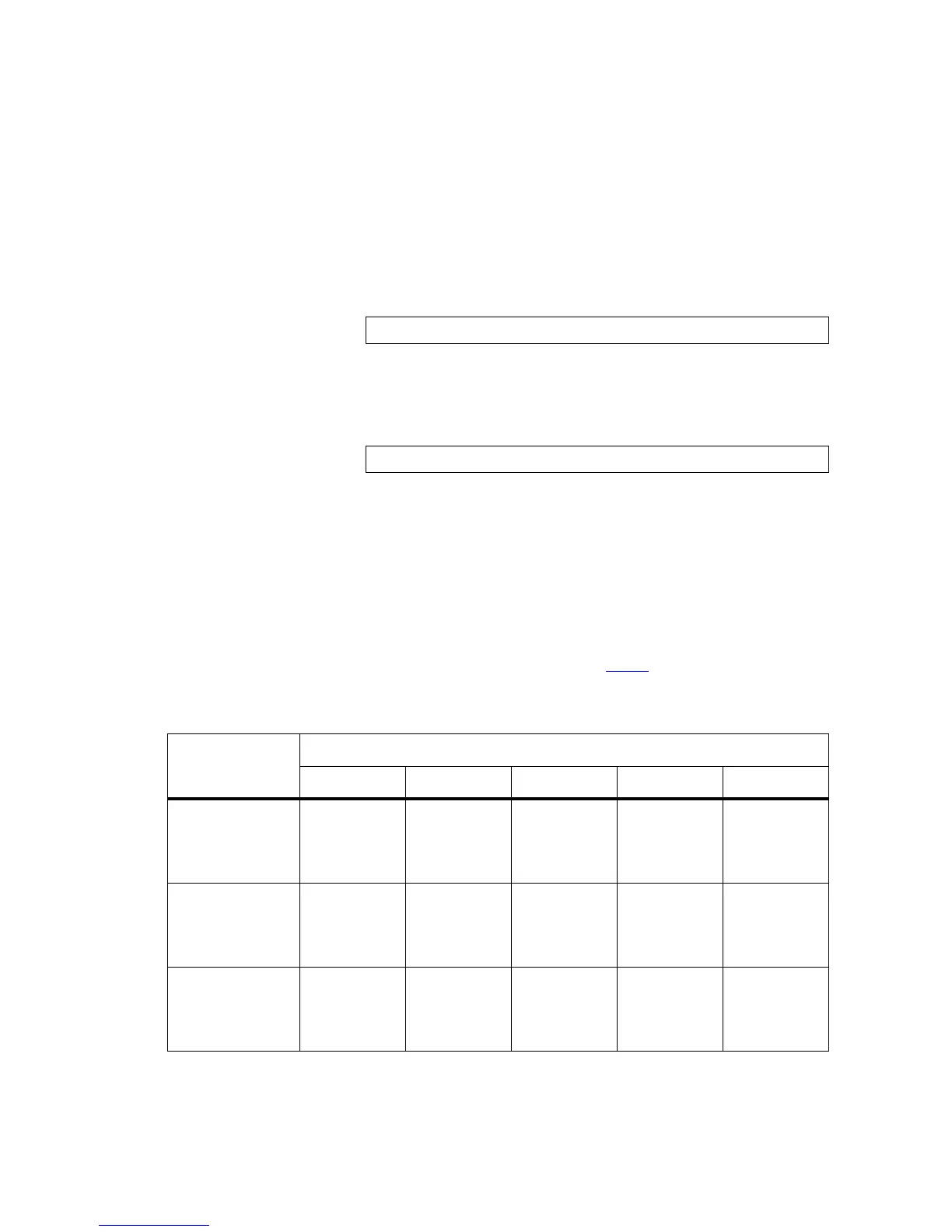
Table 10.2 Front-end tuning voltages and corresponding DAC values
Frequency band
Tuning voltages at five different frequencies
FE TUNE0 FE TUNE1 FE TUNE2 FE TUNE3 FE TUNE4
B1 band
Frequency (MHz)
DAC value
Voltage (V)
135.9
37 ± 20
0.44 ± 0.24
145.1
88 ± 15
1.04 ± 0.18
155.1
136 ± 15
1.60 ± 0.18
164.1
174 ± 15
2.04 ± 0.18
174.1
210 ± 15
2.57 ± 0.18
H5 band
Frequency (MHz)
DAC value
Voltage (V)
399.9
0 to 36
0 to 0.43
417.1
94 ± 15
1.11 ± 0.18
435.1
106 ± 15
1.25 ± 0.18
452.1
156 ± 15
1.84 ± 0.18
470.1
191 ± 15
2.25 ± 0.18
H6 band
Frequency (MHz)
DAC value
Voltage (V)
449.9
41 ± 20
0.48 ± 0.24
470.1
91 ± 15
1.07 ± 0.18
490.1
134 ± 15
1.58 ± 0.18
510.1
176 ± 15
2.07 ± 0.18
530.1
210 ± 15
2.47 ± 0.18
 Loading...


