38 Description TM9100 Service Manual
© Tait Electronics Limited August 2005
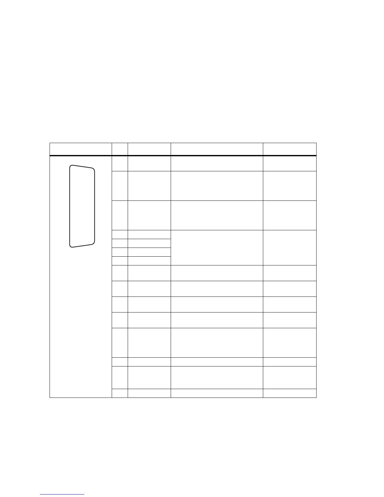
2.3.3 Auxiliary Connector
The auxiliary connector is the standard interface for external devices that are
typically connected to a radio. The auxiliary connector is a 15-way
standard-density D-range socket. The auxiliary connector provides a serial
port, three programmable input lines, four programmable digital I/O lines
and audio I/O.
The I/O lines can be programmed for a variety of functions, logic levels,
and in some cases, direction. Audio lines can also be programmed to tap
into, or out of, different points in the audio processing chain. For more
information refer to the online help of the programming application.
Table 2.3 Auxiliary connector – pins and signals
Pinout Pin Signal name Description Signal type
12 AUX_GPI1 General purpose digital input.
Programmable function.
Digital, 3V3 CMOS
5 AUX_GPI2 General purpose digital input.
Programmable function.
With LK3 fitted, GPI2 is an
emergency power sense input.
a
Digital, 3V3 CMOS
4 AUX_GPI3 General purpose digital input.
Programmable function.
With LK2 fitted, GPI3 is a power
sense input.a
Digital, 3V3 CMOS
10 AUX_GPIO4 Programmable function and
direction.
Pads available to fit a higher power
driver transistor on GPIO4 line
Digital, 3V3 CMOS
input; open collector
output with pullup
2 AUX_GPIO5
9 AUX_GPIO6
1 AUX_GPIO7
11 AUX_TXD Asynchronous serial port -
Transmit data
Digital, 3V3 CMOS
3 AUX_RXD Asynchronous serial port -
Receive data
Digital, 3V3 CMOS
7 AUD_TAP_IN Programmable tap point into the Rx
or Tx audio chain. DC-coupled.
Analog
13 AUD_TAP_OUT Programmable tap point out of the
Rx or Tx audio chain. DC-coupled.
Analog
14 AUX_MIC_AUD Auxiliary microphone input.
Electret microphone biasing
provided. Dynamic microphones are
not supported.
Analog
6 RSSI Analog RSSI output. Analog
8+13V8_SW
b
Switched 13.8V supply. Supply is
switched off when radio body is
switched off.
Power
15 AGND Analog ground Ground
a. For more information on hardware links refer to“Power-Sense Options” on page 82.
b. Can be switched or unswitched. For more information refer to “Connector Power Supply Options” on page 85.
J
B
C
D
E
F
G
H
I
1)
1!
1@
1#
1$
1%
rear view
 Loading...


