318 Transmitter Fault Finding (25W Radios) TM9100 Service Manual
© Tait Electronics Limited August 2005
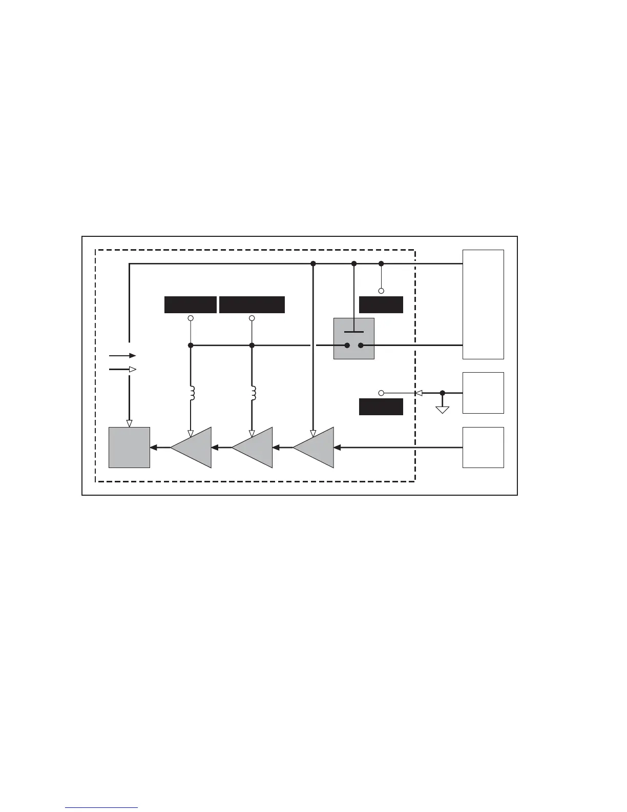
12.1 Power Supplies
Introduction First check that a power supply is not the cause of the fault. There are two
power supplies and a switch circuit for the transmitter:
■ Task 1: 13.8V DC supply from power connector (+13V8 BATT)
■ Task 2: switch circuit for 13.8V DC supply
■ Task 3: 9V DC supply from 9V regulator in PSU module (+9V0 TX)
The measurement and test points for diagnosing faults in the power supplies
are summarized in Figure 12.1.
Figure 12.1 Measurement and test points for diagnosing faults involving the power supplies for
the transmitter
GND
TEST POINT
 Loading...


