400 Fault Finding of Control Head TM9100 Service Manual
© Tait Electronics Limited August 2005
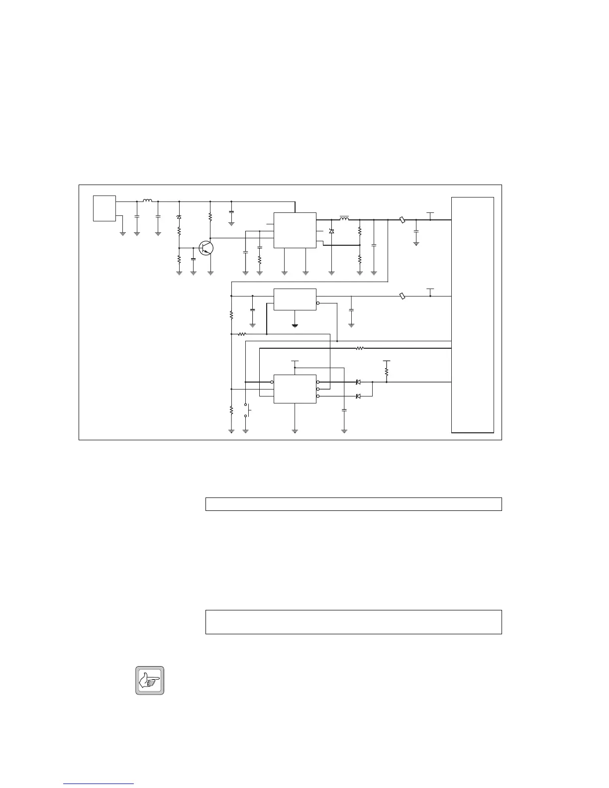
14.2 Power Supply Faulty
A 3.3V regulator (U1) converts the switched 13.8V supply from the radio
body to 3.3V. A 1.5V regulator (U203) converts the 3.3V to 1.5V.
A power-sense module (U202) verifies the outputs of the voltage regulators
and—in the case of a fault—creates a power reset signal which is processed
by the FPGA. If the start-up of the control head fails, the radio body reduces
the switched 13.8V supply shortly after power is supplied.
For all faults, check that the supply voltages are correct:
1. Check the 3.3V supply voltage between E202 and C210.
If the signal is correct, continue with step 4.
If the signal is not correct, visually inspect the components E202,
D201, L201, R205, and R206 for open or shorted contacts.
Replace if necessary. Continue with step 2.
2. Check the 13.8V supply voltage (9.7V to 17.2V) between pin 2 of
the control-head connector J103 and pin 8 of U1.
If the signal is correct, continue with step 3.
Note A fault in the control head can cause the radio body to reduce the
switched 13.8V supply shortly after power is supplied. In this case,
the control head must be supplied directly through pin 2 of con-
nector J103.
Figure 14.1 Circuit diagram of the power supply circuitry
J103
6
2
13V8
L1
C205
C207
C11
D1R16
R17
R208
Q201
C206
C12
C13R18
INH
COMP
SYNC
VCC
GND
U1
VREF
FB
OUT
2
4
3
8
1
6
5
7
GND
L201
D201
R205
R206
C14
+
E202
C210
3V3
IN OUT
U203
EN RST
GND
36
1
24
5
3V3
PFI
U202
PFO
MR RST
WDI WDI
GND
5
3
1
67
82
4
E203
1V5
C204
R201
S201
D203
D203
K1
K2
AA
AA
3V3
FPGA
R210
C201
C202
R202
R204
DNI
PWR WDT
MR
PWR RESET
1V5
3V3
1
2
R203
Control-
Head
Connector
E202/C210: 3.3V
J103 pin 2: 13.8V (V
s
=9.7V…17.2V)
U1 pin 8:
13.8V (V
s
=9.7V…17.2V)
 Loading...


