TM9100 Service Manual Fault Finding of Control Head 401
© Tait Electronics Limited August 2005
If the signal is not correct, check the 13.8V supply voltage from the
radio body. Return to step 1.
3. Check the inhibit signal at pin 3 of U1.
If the signal is above 2.2V, visually inspect the components D1, R16,
R17, R208, and Q201 for open or shorted contacts. Replace if nec-
essary. Return to step 1.
If the signal is low, replace U1. Return to step 1.
4. Check the 1.5V supply voltage at pin 4 of U203.
If the signal is correct, continue with step 6.
If the signal is not correct, continue with step 5.
5. Check E203 for continuity.
If E203 is correct, continue with step 6
If E203 is faulty, replace E203 and return to step 4.
6. U202 detects a possible power failure and generates an output signal
on pin 7. Check whether this signal is low.
If pin 4 measures 3.3V and pin 7 is low, replace U202.
If pin 4 measures 3.3V and pin 7 is high, replace U203.
U1 pin 3: high: >2.2V, low: < 0.7V
D1: V
s
– 5.1V
U203 pin 4: 1.5V
E203: 1.5V
U202 pin 4: 3.3V
U202 pin 7: 3.3V
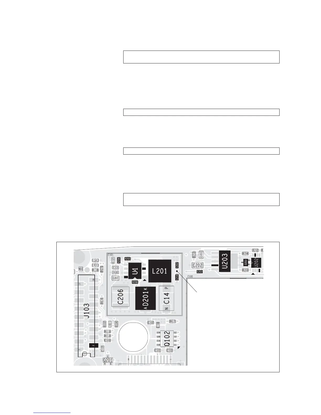
Figure 14.2 PCB layout of the power supply circuitry
top side
Junction of C210 and E202
 Loading...


