416 Fault Finding of Control Head TM9100 Service Manual
© Tait Electronics Limited August 2005
14.11 Volume Control Faulty
The voltage level of the volume control potentiometer is converted to a
digital signal by an analog/digital converter, processed by the FPGA and
transmitted to the main board.
Note This section only describes faults to the volume control caused by
the control head, which has been established during the initial
servicing tasks by means of elimination test. For fault finding of
the amplifier circuitry of the main board, refer to xxx on page yyy.
If the volume control works only intermittently, works only at full volume,
or does not work at all:
1. Check that the voltage between pins CW and WIP of the volume-
control potentiometer RV1 varies linearly between about 0V and
3.3V.
If the voltage is not correct, replace the potentiometer RV1
2. Send CCTM command 1010 to read the volume potentiometer.
If the signal is not correct, remove can E100 and replace the
analog/digital converter U601.
If the signal is correct, replace the speaker.
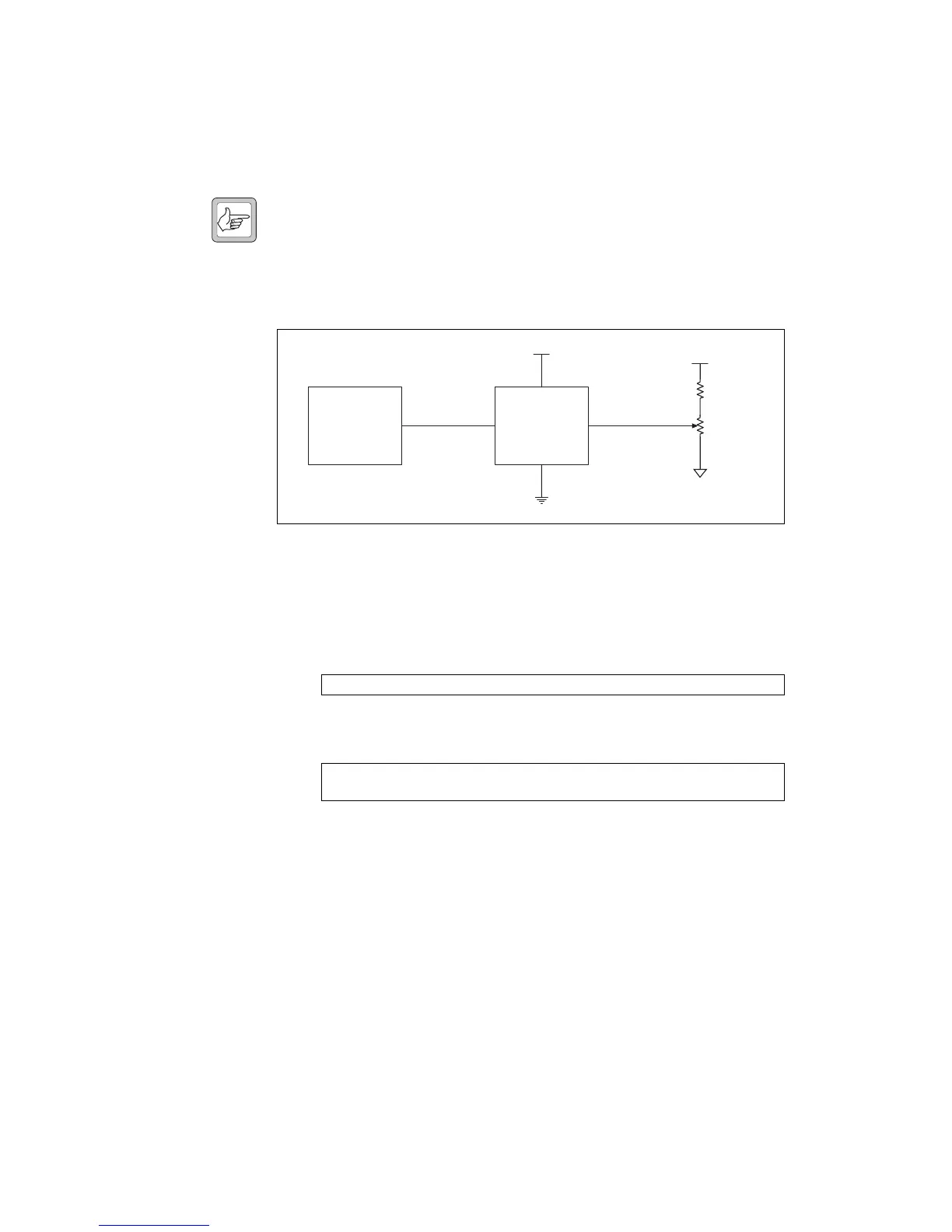
Figure 14.15 Circuit diagram of the volume control circuitry
RV1: 0 to 3.3V
No volume: reading 0 (1V)
Full volume: reading 255 (3.3V)
FPGA
ADC DO
U601
CH1
3
VCC
8
DO
6
4
3V3
3V3
VOL WIP DC
R105
RV101
 Loading...


