260 Transmitter Fault Finding (50W/40W Radios) TM9100 Service Manual
© Tait Electronics Limited August 2005
Task 5 —
Check RF Output
Power
If the power supplies are correct, check the RF output power of the
transmitter.
1. Enter the CCTM command 326 5 to set the transmitter power level
to the maximum value.
2. If not already done, program the radio with the highest
frequency in
the radio’s frequency band: Enter the CCTM command 101 xx 0,
where x is the frequency in hertz. The required values for the
different frequency bands are given in Table 11.2.
3. Enter the CCTM command 33 to place the radio in transmit mode.
4. Note the RF output power measured by the test set, and note the
current reading on the DC power supply.
5. Enter the CCTM command 32 to place the radio in receive mode.
6. Program the radio with the center
frequency in the radio’s frequency
band: Enter the CCTM command 101 x x 0, where x is the frequency
in hertz. The required values for the different frequency bands are
given in Table 11.2.
7. Repeat Step 3 to Step 5.
8. Program the radio with the lowest
frequency in the radio’s frequency
band: Enter the CCTM command 101 x x 0, where x is the frequency
in hertz. The required values for the different frequency bands are
given in Table 11.2.
9. Repeat Step 3 to Step 5.
10. Depending on the results of the above measurements, proceed to the
task indicated in Table 11.4. Note that the power and current are
considered to be skewed if they are low at one part of the frequency
band and high elsewhere.
RF output power: > 60W (VHF), > 52W (UHF)
current: < 15A (VHF), < 12A (UHF)
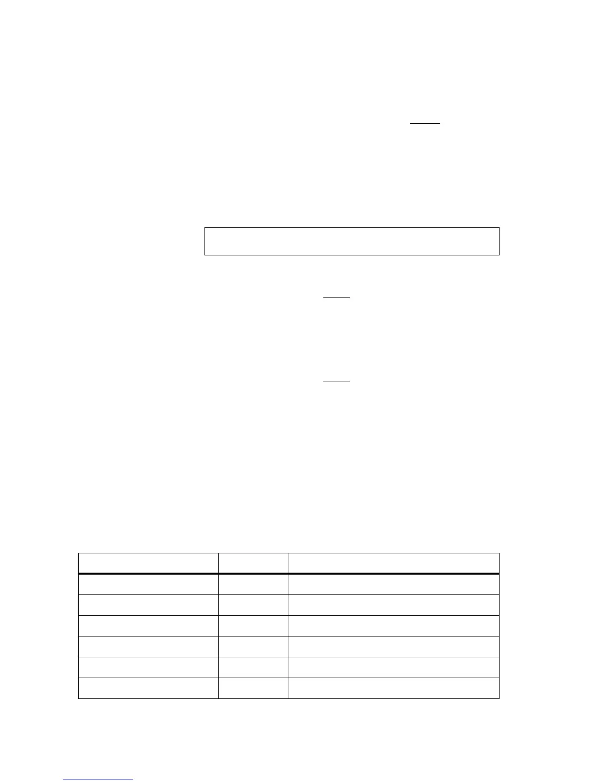
Table 11.4 Tasks to be performed according to the results of the power and current measurements
of Task 5
Power Current Task
Correct Correct Task 6 — Power unchanged regardless of setting
Correct Wrong Task 31 — Check power at directional coupler
Skewed Skewed Task 9 — Power and current are skewed
Low (> 0.1W) Low (> 0.5A) Task 11 — Power and current are low
None at RF connector (< 0.1W) Low (> 0.5A) Task 31 — Check power at directional coupler
None at RF connector (< 0.1W) None (< 0.5A) Task 7 — Check for inhibiting of transmitter
 Loading...


