TM9100 Service Manual Fault Finding of Control Head 403
© Tait Electronics Limited August 2005
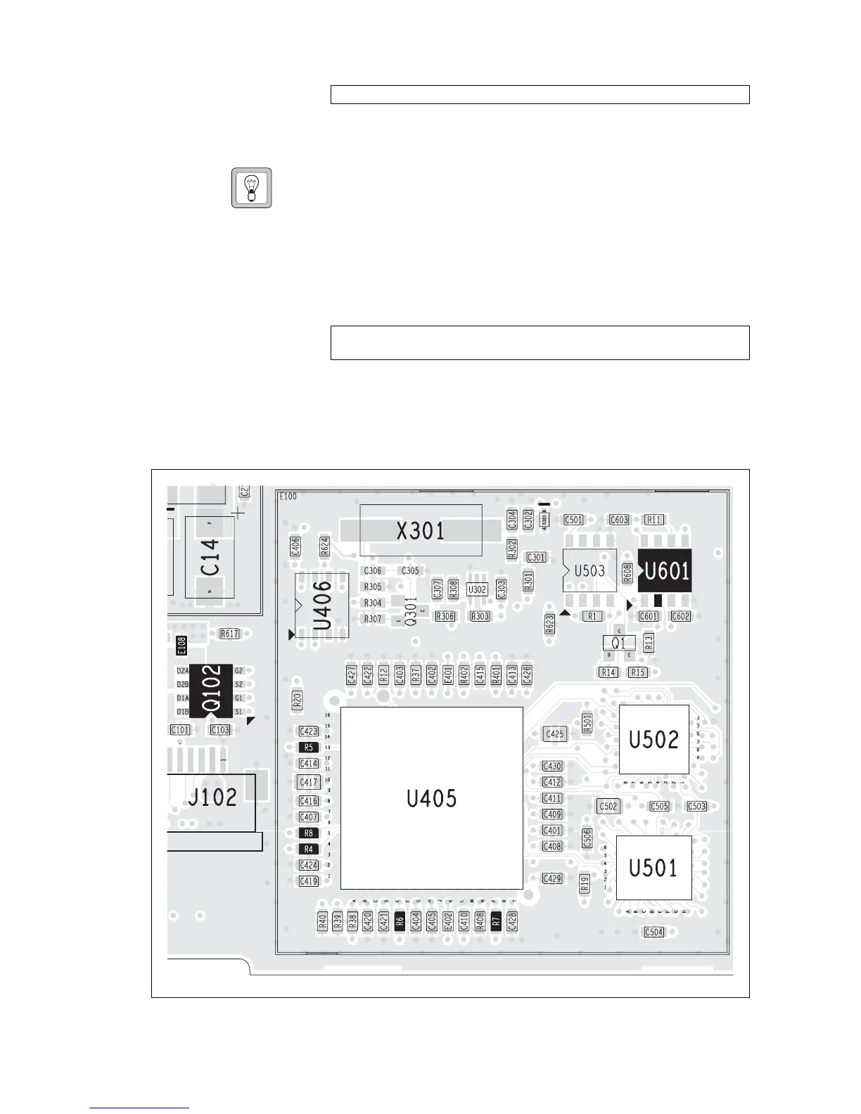
2. Check the 3.3V supply voltage at pin 2 of the LCD connector J102.
If the signal is not correct, refer to “Power Supply Faulty” on
page 400.
Tip For a quick check of the LCD without having to disassemble the
control head, connect a good LCD to the control head, or discon-
nect the LCD loom and connect it to a good control head.
3. Replace the LCD. Take care not to scratch the soft polarizer material
on the top side of the LCD.
4. Use an oscilloscope to check the signals of pins 3 to 7 of connector
J102.
If any of the signals are missing or distorted, remove can E100 and
check for continuity between the FPGA and the LCD connector.
If necessary, replace the corresponding 100Ω resistor R4 to R8.
J102 pin 2: 3.3V
J102 pins 3 to 7: The signals should be switching 0 to 3.3V in bursts of
0.125ms at approximately 1s intervals.
Figure 14.4 PCB layout of the LCD circuitry
top side
 Loading...


