32 Description TM9100 Service Manual
© Tait Electronics Limited August 2005
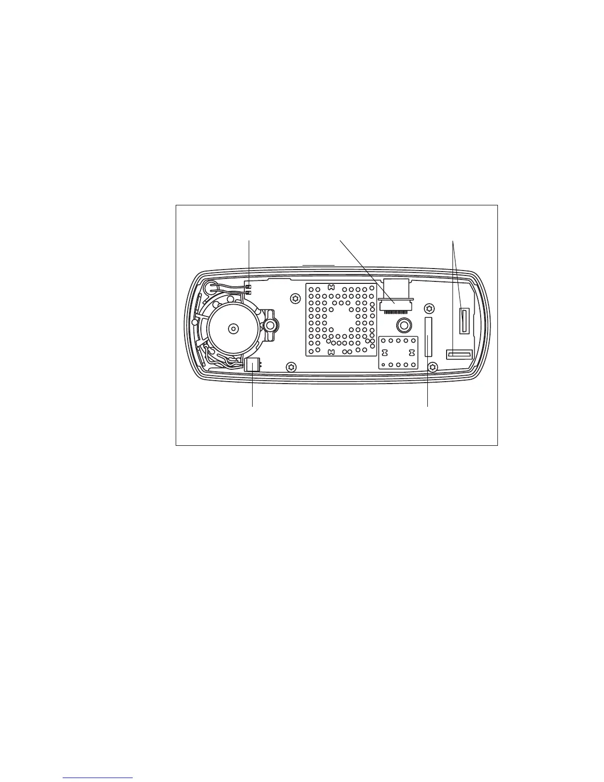
Control-Head Board
The control-head board F is a printed circuit board in SMT design with
components on the top and bottom sides. Some SMT components are
shielded by metal cans.
The control-head board is fitted to the front panel assembly
1^ through the
space-frame
J with four 3x10 PT screws E.
The side facing the radio body has the connectors for the connection of the
control-head loom, the LCD loom, the speaker, an optional control-head
options board, and pads for the leads of the concealed microphone.
The side facing the front panel has the volume-control potentiometer, the
microphone connector, the indicator and backlight LEDS, and the contacts
for the keypads.
Control-Head Loom The control-head loom D connects the connector on the control-head
board to the control-head connector of the radio body. For more
information refer to “Control-Head Connectors” on page 40.
Adapter Flange The adapter flange C is an injection-moulded plastic part, which is fitted to
the space-frame with two M4x12 Taptite screws
B.
Figure 2.5 Connectors of the control-head board
connector for control-head
options board
connector for
loom of LCD assembly
pads for leads of
concealed microphone
connector for
control-head loom
connector for speaker
 Loading...


